


Browsing Internet I did not find any authentic dependences (tables or plots) "Capacitance vs Hand Distance", "Pitch vs Hand Distance", "Capacitance vs Antenna Geometry" and so on. Just the Dewster's Excel spreadsheet contains some helpful data.
Other sources (builders frequently demonstrate Pitch vs Distance graphs) are doubtful because, at least, the authors do not specify the methods/conditions which was used for. Plus, there are some hypothesis on theremin capacitance which need be verified.
So, I am starting a project of designing a special tool which allows to take some kind of measurements.
Firstly, I am interested on relations:
1. Hand Capacitance vs Distance for different antennas,
2. Hand Capacitance vs Distance for different environment (body position, ground planes etc.),
3. Antenna Static Capacitance vs Antenna Dimensions.
Secondly, I’d like to have a tool which allows
4. to get the Pitch vs Distance data for any investigated theremin.
And thirdly (if that is possible), I need a robotized assistant (“Christopher’s dream”) which
5. could play simple melodies on theremins to estimate their voice capabilities "from apart" (I sure the perception of performer is differ than the perception of listener).
Additional requirements: $0 budget (I plan to use parts/materials from my collection), communication with standard PC applications,
portability.
Conception.
I think it should be a platform of dielectric material which holds
- motorized driver with attached "Hand Simulator",
- RF oscillator with associated antenna holder,
- electronics (placed as far from the antenna as possible).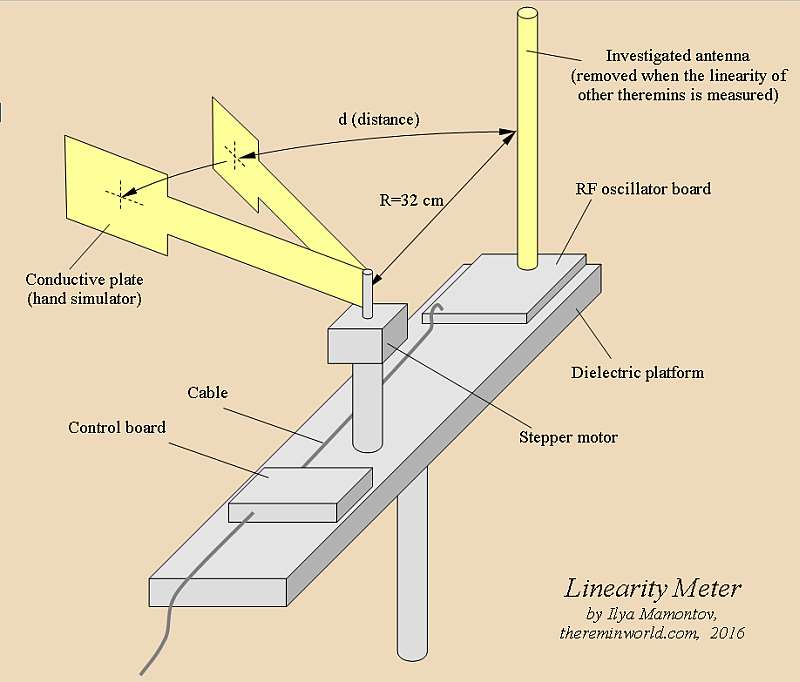
For dimensions refer the topic "Standartization of linearity measurements".
Linearity Meter
Driver.
I chose a stepper motor as it does not require a backlash-free gear mechanism and precise position sensors. Besides I have a big collection of them: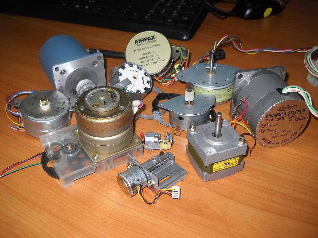
The most suitable, I think, is a stepper motor from 5" FDD:
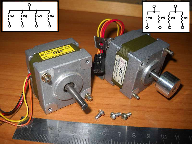
It has 4 windings (75 ohm each), 12 V power supply and step value 1.8 degree (200 steps per 1 revolution). There are two modifications of them: "with common power line" (5 wires) and "with two common power lines" (6 wires). The second is also known as "two windings with middle taps".
As I have mentioned in the "Standartization of linearity measurements" topic, with the arc radius 32 cm and step angle 1.8 the length of step will be 1.005 cm (1 cm). Unfortunately, such the motors are not intended for the micro step mode, but I'd try it.
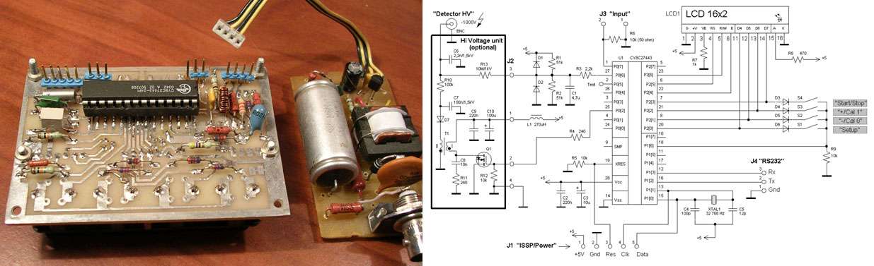
Control board.
I have two identical self made modules - one for the Cypress design contest (second prize in 2004) and other for some equipment modernization (both are unnecessary at the moment). The top USB powered module is a Cypress evaluation board/programmer for PSoC microcontrollers.
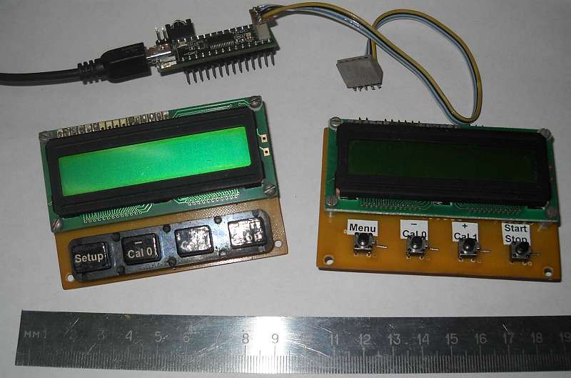
Why the PSoC? Just I have a long time experience, plus there are tons of Application Notes/examples on the Cypress web page, including those helpful papers:
AN2197 "Stepper Motor Driver",
AN2229 "Multifunctional Stepping Motor Driver",
AN43679 "Industrial Stepper Motor Driver",
AN2283 "Measuring Frequency".


That will not give meaningful results to the professional musician. Because Theremins are played by human musicians and not by engineers and their robots. Only a very experienced classical precision Theremin player will be able to tell about playability in general and may judge specific aspects like pitch linearity and coherent volume response.
Tone spacing and the homogeneity of the pitch and volume fields is sensed differently by each player.
But from an engineer's point of view, Ilya's experiment is for sure interesting. :-)

"Firstly, I am interested on relations:
1. Hand Capacitance vs Distance for different antennas,
2. Hand Capacitance vs Distance for different environment (body position, ground planes etc.),
3. Antenna Static Capacitance vs Antenna Dimensions.
Secondly, I’d like to have a tool which allows
4. to get the Pitch vs Distance data for any investigated theremin." - ILYA
Thanks for citing my data! My $0.02:
1 & 2: I believe you can know this pretty much exactly via calculation in Fast Field Solvers FastCap. I don't think this is a first order worry, more of a second order, if that. FastCap vindicated my actual body/arm/hand measurements so I feel like I'm pretty much past this point. And any Theremin that requires one to move their body in order to linearize certain areas of the pitch field isn't one I want to design, build, or play.
3: You can measure this with an LC oscillator and work your way backwards. And again, FastCap can tell you pretty much exactly. FastCap can also show you the actual intrinsic vs. mutual C (not that it matters in practice).
4: Once you have a setup that you can demonstrate accurately reflects body C and arm / hand motion (might have trouble convincing others, not sure if that's part of your goal) this is where things get interesting. I imagine most Theremins would provide a range of curves depending on how they are tuned. Theremins with EQ coils would give infinite curves depending on the location of the two resonances.
Maybe animate a cadaver arm? Stepper motors yanking on the tendons? ;-)
And I'm really not trying to discourage you, but I've spent enough of my life figuring out, working with, fixing, etc. other people's crap that it doesn't interest me much anymore. Most, if not all, of the designs out there probably aren't worth your time either. It's a dabbler's field because a basic analog Theremin can be implemented so simply and easily by those with little electronics knowledge (not that I'm calling all Theremin designers dabblers, just that there seem to be tons of them to deal with).
=============
In terms of body simulation, I think you just need a grounded plate, sized so that it gives roughly the same C as your body at the same distance. I think it could be located anywhere, not necessarily connected to or even near the arm.
Certainly the hand will dominate everything, but the lack of a jointed elbow that itself moves nearer and farther from the antenna, and the lack of an upper arm, may both confound things a bit. It's likely none of this has to be 3D (plates would almost certainly work as well) but having them be 3D would help you size them correctly, and would help convince others (and yourself?) that your setup isn't fundamentally unsound. I'd put a passive arm on a string and pulley arrangement, which would inherently give you linearity of movement (no software calcs necessary for the hand/antenna distance) and you could position the stepper motor any distance you like from the experiment. Again, just my $0.02.
ILYA, once you have characterized capacitance between hand/arm/body and antenna, couldn't you "play it back" via something simple like a varactor connected to the antenna? If it mostly comes down to C (as seen by the antenna) as proportional to inverse hand distance plus some constant, then that seems like the easiest way to go. All you need is variable 1pF or so (plus some bulk adjustable C which could be a trimmer or similar, or a grounded fixed plate). Might be able to electrically adjust the grounding of a fixed plate instead of moving it around? Just spitballing...
Dominik, Thierry, Eric,
thanks for the feedback.
Yes, that tool is more for engineers (builders) than for musicians. For better understanding of phenomenons, to know ways to bypass problems, and thus to make theremins better.
"couldn't you "play it back" via something simple like a varactor connected to the antenna?"
This can be applied only to p.5. But technical artistry will be lost. Sure Thierry and Dominik will understand me  .
.
Offtopic.
"Thierry and Dominik will understand me"
Here I planned to insert a quote from my lovely episode from the novel "From the Earth to the Moon" by Jules Verne. I have found English text, but - what the f**k! - instead of the Frenchman-Yankee dialogue, I found only a dull technical description.
From the original French version (chapter XXIII):
– .... Je regrette seulement que ses formes ne soient pas plus effilées, son cône plus gracieux; on aurait dû le terminer par une touffe d’ornements en métal guilloché, avec une chimère, par exemple, une gargouille, une salamandre sortant du feu les ailes déployées et la gueule ouverte…
– A quoi bon? dit Barbicane, dont l’esprit positif était peu sensible aux beautés de l’art.
– A quoi bon, ami Barbicane! Hélas! puisque tu me le demandes, je crains bien que tu ne le comprennes jamais!
– Dis toujours, mon brave compagnon.
– Eh bien! suivant moi, il faut toujours mettre un peu d’art dans ce que l’on fait, cela vaut mieux. Connaistu une pièce indienne qu’on appelle – Le Chariot de l’Enfant?
– Pas même de nom, répondit Barbicane.
– Cela ne m’étonne pas, reprit Michel Ardan. Apprends donc que, dans cette pièce, il y a un voleur qui, au moment de percer le mur d’une maison, se demande s’il donnera à son trou la forme d’une lyre, d’une fleur, d’un oiseau ou d’une amphore. Eh bien! dismoi, ami Barbicane, si à cette époque tu avais été membre du jury, estce que tu aurais condamné ce voleurlà?
– Sans hésiter, répondit le président du GunClub, et avec la circonstance aggravante d’effraction.
– Et moi je l’aurais acquitté, ami Barbicane! Voilà pourquoi tu ne pourras jamais me comprendre!
...Show must go'on (c)
Schematics which I plan to use for: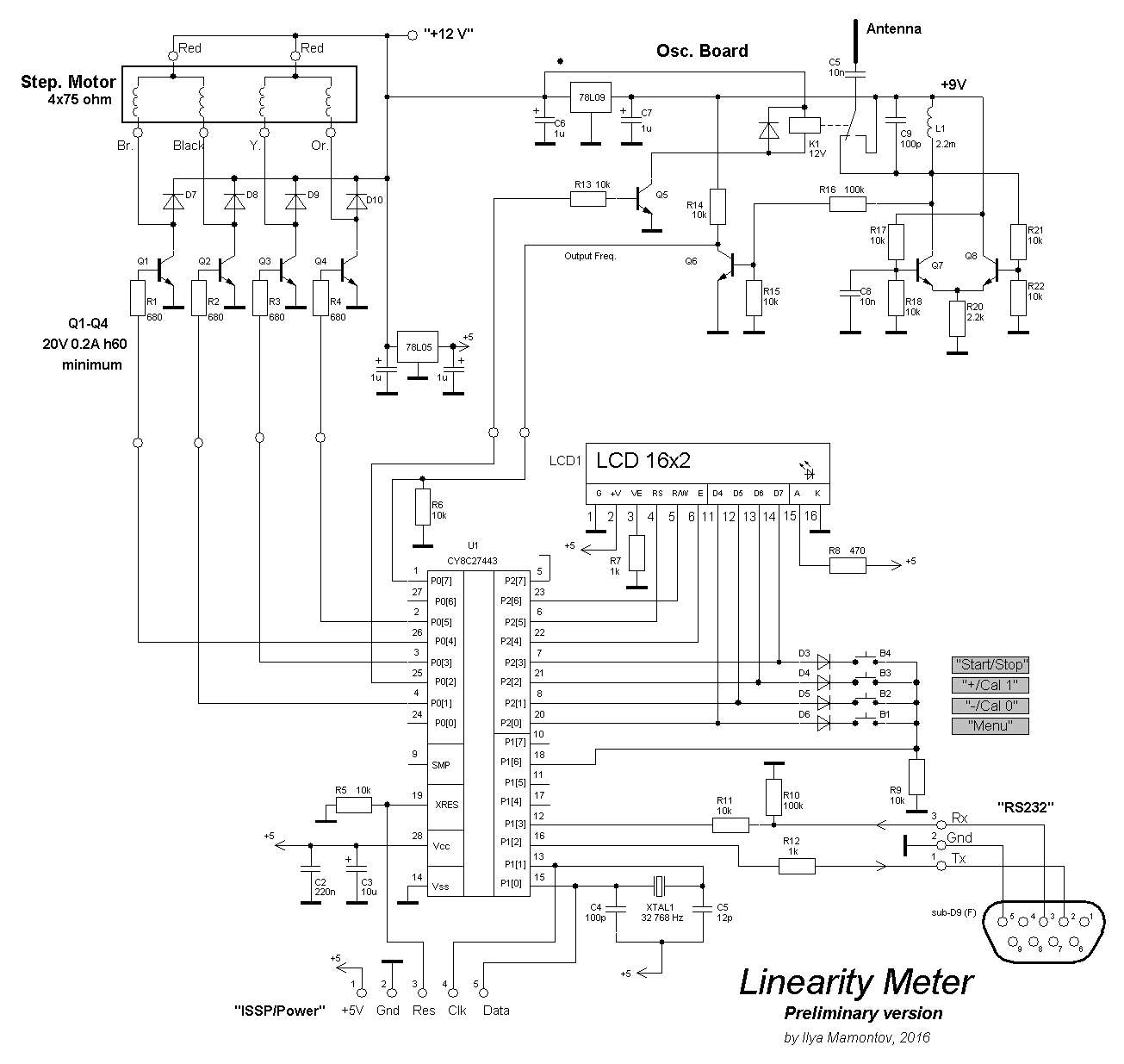
Breaf explanations.
The RF oscillator is built using a well known differential circuit a-la Etherwave. It has the individual voltage regulator 12-to-9 V (78L09). The L1,C9 and antenna capacitance compose the resonance circuit. Q6 is a buffer.
Microcontroller U1 measures the frequency on input P0[7]. The relay K1 disconnects the antenna to make the reference measurements (to compensate the drift). Microcontroller controls the relay via the switch Q5 (using output P0[2]).
Also, microcontroller controls the phases of stepper motor via switches Q1-Q4. Certainly, the best option would be to use a specialized chip like ULN2003/K1109KT23(Rus.), instead of Q1-Q4, R1-R4, D7-D10 and even R13, Q5, but I dont have it at the moment.
Resistors R11 and R12 allow direct connection to PC COM port (or USB-to-COM bridge) and exclude MAX232 level translator. Inversion option of Rx and Tx is provided in PSoC UART module.

"That will not give meaningful results to the professional musician. Because Theremins are played by human musicians and not by engineers and their robots. Only a very experienced classical precision Theremin player will be able to tell about playability in general and may judge specific aspects like pitch linearity and coherent volume response. Tone spacing and the homogeneity of the pitch and volume fields is sensed differently by each player.
I seem to remember reading Lydia Kavina describing her theremin, saying that the bass notes were spaced a little further apart than the higher notes and that this seemed to be just right to her. (I have looked for this recently to see if my memory is correct and have been unable to find it.)
Also, it may be that one's physique influences linearity - is the linearity different for someone weighing 250 pounds with a large "beer muscle" as compared to someone weighing 125 pounds?
"Schematics which I plan to use for:" - ILYA
- I think I would pick an inherently higher tank voltage swing oscillator, and one that didn't have 100pF tank C but relied more on antenna C.
- Interesting having a relay to engage / disengage the antenna from the oscillator.
- R15 + R16 = 110k; R21 + R22 = 20k; 110k || 20k = 16.9k; This seems like a real Q killing damping load on the tank, which could perhaps confound your F to C calculations.
- Is C5 necessary?
- Interesting the reuse of the LCD bus for buttons.
You must be logged in to post a reply. Please log in or register for a new account.