Let's design and build cool (but expensive) FPGA based theremin

Posted: 8/9/2019 7:51:13 AM
Buggins

From: Porto, Portugal

Joined: 3/16/2017

Hardware build progress

Assembled Audio Connectors board (Line In, Line Out) - both big and small audio sockets soldered:


Pedal connectors board assembled:


Soldered SP721 ESD protection on oscillator boards:

Main question now: how to pack everything into prototype box I bought.


It looks like cabinet mounting holes should be placed wider than 110mm in this design:

Going to make yet another pipe monster.

Project page is updated

Posted: 8/9/2019 3:44:06 PM
dewster

From: Northern NJ, USA

Joined: 2/17/2012

"Main question now: how to pack everything into prototype box I bought."  - Buggins

Ha!  I've been looking at those junction boxes for what seems like forever and ordered one a while back.  They're usually too small for the main control box, and too heavy for the antenna boxes.

You could maybe stick the coils outside?  Maybe integrate them somehow into your "pipe monster"?

I still like tinkeringdude's brilliant suggestion of a digital drum type theremin setup, where the user is able to locate anything anywhere.  Would be a lot less "tippy".  Though drum stands are made for people beating on them, and no one really touches a Theremin in operation, so it's overkill to the max.

That's a lot of pedals!  What do you plan to do with them?

Posted: 8/9/2019 5:44:20 PM
Buggins

From: Porto, Portugal

Joined: 3/16/2017

That's a lot of pedals!  What do you plan to do with them?

Added 6 pedals just because I can
Actually, there are 6 single-ended ADC inputs available in Cora Z7 board. Just used all of them. If it's too much, some of them might be used for front panel pots.

One or two of pedals of course may be used to control some effect. Not sure if it's convenient to use pedal while playing on theremin

The rest 5, e.g. may act as buttons.[/size]
What about controlling live looping - 5-6 buttons are probably not enough.

Although, since pedals are not buttons, but analogs, single pedal can activate different actions, e.g. when half pressed or fully pressed.

Posted: 8/12/2019 7:23:36 AM
Buggins

From: Porto, Portugal

Joined: 3/16/2017


You could maybe stick the coils outside?  Maybe integrate them somehow into your "pipe monster"?

Good idea. I like the way how it's used in "Build Project: Dewster's D-Lev Digital Theremin" thread.

Probably will try it in one of next builds.

20mm pipe can fit into 32mm pipe. My oscillator board is a bit wider than 32mm pipe inner, but can fit there if 32mm pipe is cut a bit inside.
Coils winded on pipes would look great.

So far, I've assembled pipe monster with coils to be placed inside box.


Just a few polypropylene fittings and pipes.

Weld them at your own taste.

Mount suitable box as cabinet for theremin internals.


More details on my project page.

Posted: 8/13/2019 4:19:20 PM
Buggins

From: Porto, Portugal

Joined: 3/16/2017

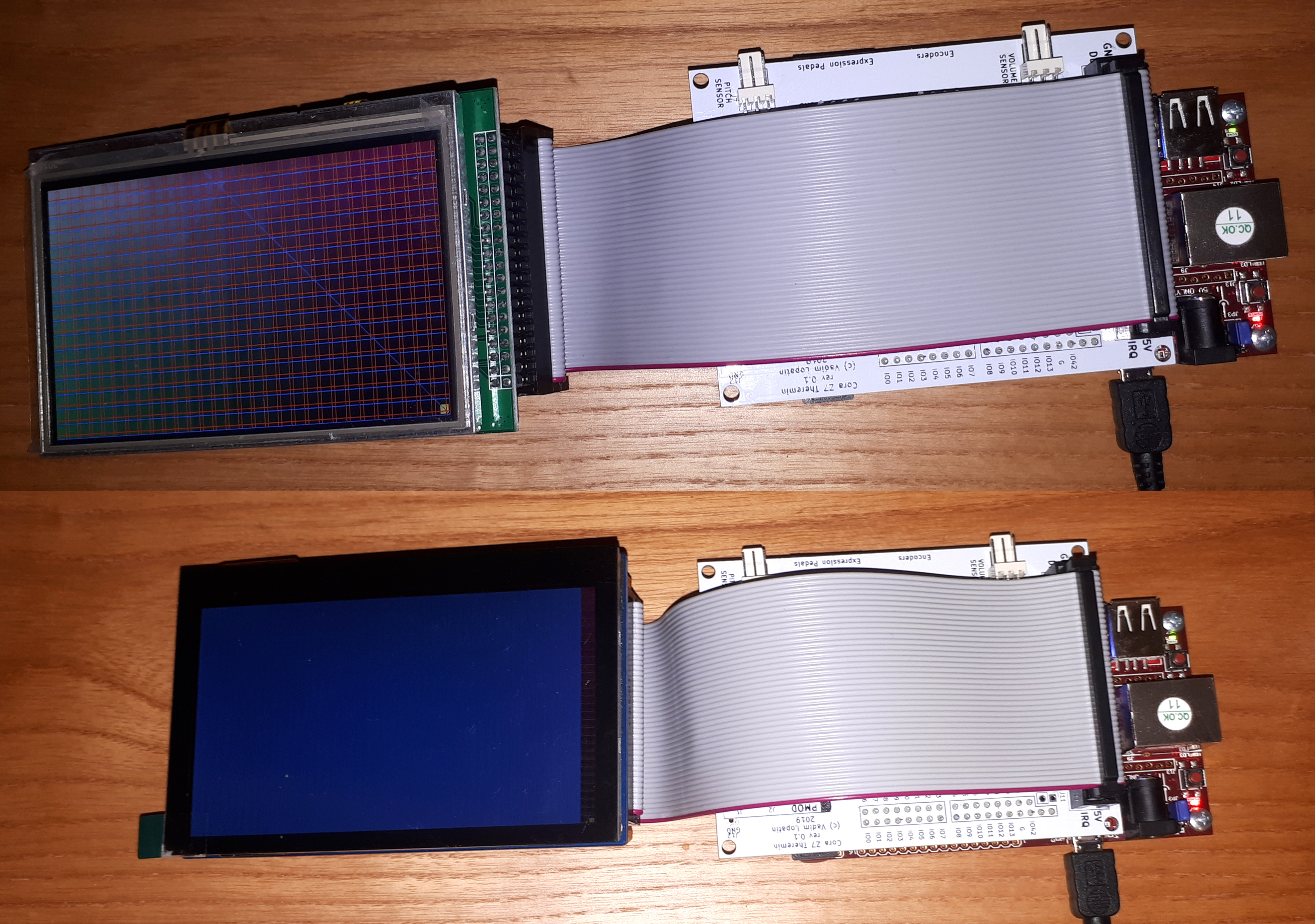
FPGA programming progress update.

Created IP which combines theremin sensor, LCD controller, encoders controller, audio controller, two i2c interfaces.
(Missing components: sd_card, ADC for pedals board)

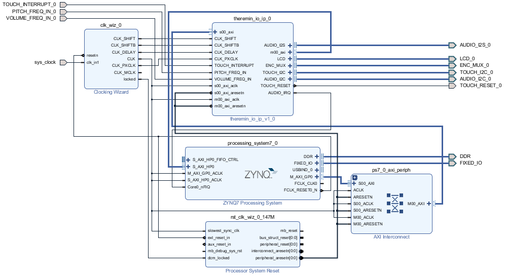
Created block design:


Utilization:


Code:

+----------------------------+------+-------+-----------+-------+
|          Site Type         | Used | Fixed | Available | Util% |
+----------------------------+------+-------+-----------+-------+
| Slice LUTs                 | 1317 |     0 |     17600 |  7.48 |
|   LUT as Logic             | 1217 |     0 |     17600 |  6.91 |
|   LUT as Memory            |  100 |     0 |      6000 |  1.67 |
|     LUT as Distributed RAM |   40 |     0 |           |       |
|     LUT as Shift Register  |   60 |     0 |           |       |
| Slice Registers            | 1638 |     0 |     35200 |  4.65 |
|   Register as Flip Flop    | 1638 |     0 |     35200 |  4.65 |
|   Register as Latch        |    0 |     0 |     35200 |  0.00 |
| F7 Muxes                   |   13 |     0 |      8800 |  0.15 |
| F8 Muxes                   |    0 |     0 |      4400 |  0.00 |
+----------------------------+------+-------+-----------+-------+


Placement on device (used cells are cyan):

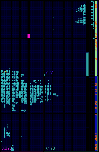
Part of resources is occupies by AXI bus support blocks (interconnect, clock gen, etc).

Theremin IO IP itself takes 925 LUTs and 1177 registers.

I hope up to 90% of FPGA resources may be used for future advanced synthesizer implementation.

Posted: 8/15/2019 2:12:21 PM
Buggins

From: Porto, Portugal

Joined: 3/16/2017

Project progress

Writing drivers for using of FPGA components from ARM PS side.
Audio IRQ is working.
LCD controller DMA is working.
Added support of two on-board RGB LEDs (PWM, RGB444 each).

Posted: 8/16/2019 3:23:45 PM
Buggins

From: Porto, Portugal

Joined: 3/16/2017

I'm trying to utilize second ARM core of 2 available on Zynq 7010 for audio interrupt handling (synthesis) only, leaving first core for GUI and control tasks.
No success so far.

Posted: 8/19/2019 3:00:40 PM
Buggins

From: Porto, Portugal

Joined: 3/16/2017

Driver for Zynq standalone mode is updated.
I've implemented AMP mode with two ARM cores.
CPU0 is running GUI application.
CPU1 is running synthesizer application - only handles Audio IRQs.

Idea for theremin software development using emulator.
Device has USB UART configured for bit rate 921600.
It can send information from theremin sensors and controls as text via serial port.
Emulator application may connect to serial port and use transferred data (e.g. measured pitch and volume signals period) as input for emulator.
When theremin FPGA device is connected to PC, emulator may be used to develop synthesizer code.
Since PC is only able to playback audio data as frames (3..6ms), emulator should interpolate theremin sensor values for N samples between previous value and new one, then call audio IRQ code for each sample to fill audio frame before sending to audio output.
IRQ code will be the same code as running on real device.
GUI code will be the same as running on device.
It will be easy to debug / modify / build / run theremin firmware w/o flashing of device.

Posted: 8/20/2019 10:42:57 AM
Buggins

From: Porto, Portugal

Joined: 3/16/2017

Testing on hardware. A lot of issues found.

Encoders board - does not react on buttons/encoder rotation.

LCD screen - no picture displayed - several vertical lines are shown (even const color passed to RGB). Tried to reduce PXCLK to 18MHz, increased FP, BP, Sync... Maybe something is wrong with timings. Or FPGA pins to LCD pins routing. To be fixed. (only backlight brightness is working fine, LOL)
UPD: found the cause - bad contacts in IDC cable

I2C controller connected to Phones Out amplifier (AMP3) returns error.

Posted: 8/22/2019 3:03:38 PM
Buggins

From: Porto, Portugal

Joined: 3/16/2017

Something is wrong with my LCD. Only about ~10% on the left of screen shows proper image, the rest duplicates the same row image (each column has the same color).
Ordered another one just in case. Yet another $32 spent... Have to wait 2-3 weeks for delivery.

UPD: connected another LCD - with resistive touch, with partially compatible pin header (except touch interface). It's working perfectly.
So, it's confimed that my Waveshare capacitive touch 4.3" LCD is broken.
Spent whole day trying different timings on broken display...

On photo: upper LCD is ok, but has resistive SPI touch screen incompatible with my design, second one is capacitive touch I'm going to use in my design, but it doesn't work (only part of screen - right side on photo - shows proper image).


Started working on emulator (cross platform Qt app).

You must be logged in to post a reply. Please log in or register for a new account.