YAEWSBM - Yet Another Etherwave Standard Bass Mod

Posted: 3/14/2012 9:52:52 PM
dewster

From: Northern NJ, USA

Joined: 2/17/2012

CAUTION - I make absolutely no guarantees for this circuit mod, use at your own risk! - CAUTION

I'd like to present my Etherwave Standard (EWS) low frequency mod.  It was inspired by the existence and performance videos of Thierry's ESPE01 board but isn't a reverse engineering of his undoubtedly excellent offering.  It’s merely what this or any other average EE might likely do when confronted with the oscillator coupling issue that plagues the EWS.  I hope no one here thinks I am in any way trying to encroach upon or steal any of the well deserved thunder of the ESPE01 or Thierry's efforts - quite the contrary.

In the stock configuration the EWS fixed and variable pitch oscillators are mixed via two 15 pF capacitors feeding a diode, which causes coupling between the oscillators.  This coupling creates a dead zone around zero beat which has a some good points.  For one it helps to keep the instrument silent if you move far away from it.  For another it helps to prevent operation on the other side of zero beat, where moving away from the antenna produces an increase in pitch.  Finally, the coupling alters the wave shape in the bass region to a rather pulse-like string sound that some may find useful.  However, coupling has several bad points.  The worst is that it restricts the operation in the bass range.  The low end behaves rather non-linearly as the coupling increases with decreased frequency, making control down there difficult.  And the tone gets very thin sounding before it poops out.  In my opinion the bad effects of coupling far outweigh the good and I can't imagine ever wanting to revert my EWS back to stock.

The circuit is basically just two non-inverting buffers formed from simple emitter followers.  The impedance that the capacitors from the LC tanks (C6 & C2) see is fairly high (~100k) so as to not limit their swing too much.  Mixing then takes place on the emitter side, where the transistor beta mostly isolates the loads from the sources.  Slightly larger capacitors are used on the mixing side to boost amplitude a bit.  If you hear "motor boating" (ba-bup ba-bup ba-bup) when playing frequencies very near zero beat you should adjust the 10k pot away from center and try again.  I experienced this slightly with the bread boarded version, but the final version employed a different set of transistors that are likely better matched because no adjustment was necessary.  In most cases you can probably dispense with the pot and just make the emitter resistors 10k each.  You could probably also balance the mixer by replacing the 100k resistors with 47k resistors, lifting their grounded ends and connecting them to either side of a 100k pot with the wiper at ground, though I didn't pursue that method at all.

+/-12V and ground are available at the 8 hole inline expansion point on the Etherwave, and this is where I located the prototype board.  C6 and C2 were removed from the EWS board with a solder sucker and iron, the capacitor legs were then bent outwards 45 degrees, so that they form a 90 degree angle with each other.  One leg of C6 was then resoldered at the position where it came from, in the hole closest to the edge of the board, with the free leg of the capacitor pointing towards the prototype.  Same for C2 (solder it into the hole closest to inline expansion point).  Two 22 gage wires were then run from the free legs of the two caps to the prototype, and a third to the free hole at the C2 location (closest to the center of the board).  Because these capacitors are directly connected to the sensitive side of the LC tanks you'll want to keep these wires short and direct.  I constructed the prototype on a piece of glass epoxy vector board (I don't recommend the phenolic kind that Radio Shack sells as the foil tends to delaminate when soldering) and used the leads from some old LEDs to solder it 1/2" or so above the expansion point (they are stiffer than regular wire).  Don't position it too high or it might interfere with the top of the EWS case when closed.

The jumper allows you to switch between pre mod and post mod operation.  Obviously the buffers are still in circuit so this isn't a complete reversion with the jumper installed, but it sounds very close to me - certainly there is coupling going on in the bass region with the jumper installed and very little or none with it removed.  Store the jumper on one of the pins when not needed.  You can purchase special square pin headers, but I instead used the snipped off leads of an old LED here for jumper pins.

If you might sell your EWS at some point in the future you're probably better off with Thierry's ESPE01 mod.  It's likely better thought out and certainly better constructed, and you'll be able to point to various web links and YouTube videos of it in action to your prospective buyers, thus enhancing its value.  If you think you might want to go easily back to mostly stock response with a simple jumper change, and feel like a bit of hacking, you might want to give my circuit a shot.  I recommend you set it up on a breadboard and try it out before you fully commit, this lets you back out of the mod easier if you don't like it, and gives you the chance to play around with the circuit topology and values.  Who knows, maybe you'll stumble across something you'll like better!

Now for some pix!

Etherwave Standard Bass Mod 01

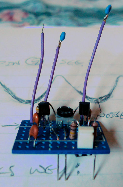
Above is a view of the prototype with C2 and C6 already soldered to the ends of the wires.  Those are snipped off LED leads poking out the bottom for mounting.


Etherwave Standard Bass Mod 02

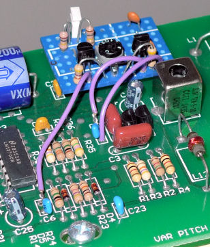
Above is the prototype soldered in position.  You can see here how one lead of C6 & C3 are soldered back to the main board, and the third wire goes to the empty hole at C3.


Etherwave Standard Bass Mod 03

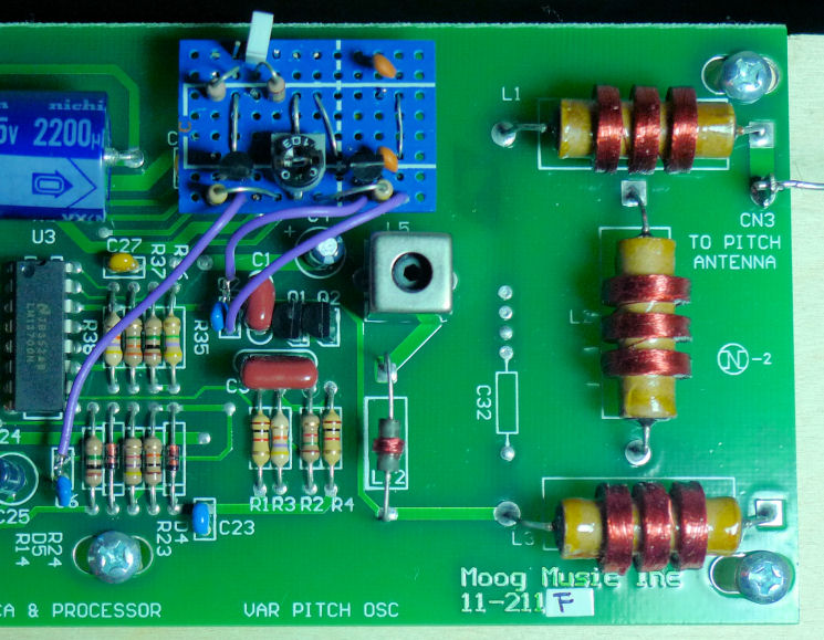
Above is a more arial view of the install.  Note the jumper is on a single pin for storage.


Etherwave Standard Bass Mod 04

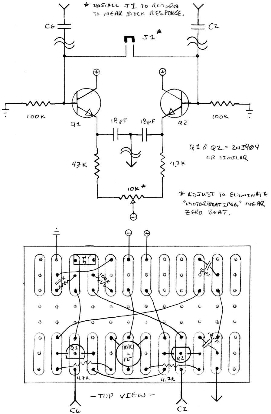
Above is the schematic and how I decided to do the vectorboard layout.  This is an x-ray view of the vector board looking down from the top (the copper pads are on the bottom).

============

[EDIT - 2014-04-04]

If you experience "motorboating" or a "ba-BUP ba-BUP" sound near 0 Hz (the null point), you should try decoupling both of the collector leads independently as FredM suggests:

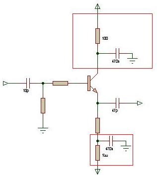
The top box shows a 100 ohm series resistor going from the positive rail to the collector, and 0.47 uF from collector to ground.  So for the two transistors in the mod you would need two resistors and two capacitors.  This fix reportedly worked for TW member Marekbuk.

Posted: 3/14/2012 10:33:12 PM
RS Theremin

From: 60 mi. N of San Diego CA

Joined: 2/15/2005

RS Theremin said in thread: ESPE01 installation success!

Dewster, I am also waiting to see your schematic on an EW low freq fix. Did you know most schematics for theremin advancement come out of the America’s and that Europe with some of the finest modern instruments keep most of their schematics secret? hum….

Does pond separation create a silent competition which could actually be a good thing?

------------

dewster: This is very clean, would you mind if I made an iron-on pdf from your schematic. I will place - dewster 2012 - in the copper. It is a great electronic starter project for EW owners.

Everything is at Radio Shack except the 18 pf caps, why is this value selected?

Posted: 3/14/2012 10:50:53 PM
dewster

From: Northern NJ, USA

Joined: 2/17/2012

@RS Theremin:

"Everything is at Radio Shack except the 18 pf caps, why is this value selected?"

For a bit of gain over 15 pF, not too critical.  I got them from a really handy tiny cap assortment RS used to sell, too bad they don't anymore.  They ought to change their name to "Cell Phone Shack" or similar.

Feel free to do anything you want with this mod, crediting me is nice but not necessary.  Hopefully others will build it and chime in with useful changes and suggestions.  One thing I didn't try was using FETs instead of BJTs.  I also didn't try resistively coupling the emitters - I imagine you could do the mixing directly that way.

Posted: 3/14/2012 11:42:52 PM
Thierry

From: Colmar, France

Joined: 12/31/2007

Congratulations! That looks like an early ancestor of the ESPE01 module.

I'm sure that one may obtain great results with this simple circuit under very specific conditions, but did you consider the different circuit variants of the Etherwave? The signal levels vary from one circuit board release to another. A huge difference exists between 211A and the later variants due to increasing slightly the oscillator's frequencies and reducing the number of linearization coils. Another big step was between 211C and 211D when Moog replaced the variable inductors from Toko by others from Coilcraft and had to modify the working points and thus the amplitude of the oscillators.

Fred Mundell published a very similar circuit as yours already 2 years ago on Element14. But he added that he could give no warranty since he had no occasion to run thorough and exhaustive tests.

Did you test your circuit on all board variants (A,B,C,D,F,G,H,J) for long term stability?

Did you make sure that the load of your circuit seen by the oscillators will not vary with temperature (varying junction capacitance of your buffer transistors)?

Did you analyze the waveform at the input of the LM13700? Are amplitude and harmonic spectrum the same as before? And how does it look in older Etherwaves which have still a LM13600 instead?

Did you travel around for concerts and workshops with your own modified instrument during a year in order to check mechanical stability and to get opinions from professional thereminists?

I would find it very dangerous to publish such a simple and most probably not long term tested circuit. Will you be responsible if someone installs your circuit and perhaps only a year later or so one of the oscillator's transistors goes up in smoke?

Please let the readers know the answers so that they can estimate the risk for their loved instrument. 

Actually I would not call it a great starter project, Christopher. It's (like the Glasgow Theremin circuits) a half-baked snapshot which should be given the time to stand the test of time before being published on this platform or elsewhere.

Posted: 3/15/2012 12:29:38 AM
dewster

From: Northern NJ, USA

Joined: 2/17/2012

@Thierry:

Good points, my EWS PWB has the number "11-211F" on it - rev F?

This is the first I've heard of Fred Mundell or Element14 (I'm rather new to this area, that's my fault) but like I said in the mod text, buffering is probably the first approach the average EE would try when faced with unwanted coupling.

My thinking during the design was to simply buffer the signals pre mix.  I adjusted impedances once I got it breadboarded and hooked up to the EWS so that levels were roughly the same as before.  I did look at the waveform at the mixer diode both pre and post mod to make sure it was around the same amplitude and about the same clipping.

I think it's pretty clear that I'm just some random guy posting a circuit on the internet and caveat emptor to the max, no guarantees, etc.  I would hope that anyone attempting to mod their EWS would have sufficient electronic background to evaluate the circuit to some degree and not just take it at face value.  But it's not like we're cutting traces here, if there are problems the mod is easily backed out. 

And "goes up in smoke"?  I seriously doubt a couple of harmless unity buffers fed by and driving a few puffs could cause any variant of the EWS to catch fire (though I am obviously no expert on the variants).  Do you seriously think fire is a real possibility?

Are there forum rules for posting circuit mods?  If so, I'd very much like to read them before I post any others.

Posted: 3/15/2012 12:37:21 AM
RS Theremin

From: 60 mi. N of San Diego CA

Joined: 2/15/2005

Thierry, to me a starter project would be anything under 10 components. Send an EW oscillator transistor up in smoke; I can’t believe you could even propose such nonsense. What’s going on? There is jumper connection and everything goes back to how it was if it does not perform for someone. Be an optimist; think of the business you will get if someone damages their theremin. I have the latest model EW and if it only works for me so be it. Time will reveal the full capabilities. The theremin will always be evolving. What sets dewster apart, he did not mock the screen door spring!

Posted: 3/15/2012 12:47:30 AM
dewster

From: Northern NJ, USA

Joined: 2/17/2012

OK I put big red caution notices on my mod post.  Does anyone know how to make them blink?

Posted: 3/15/2012 1:10:51 AM
SewerPipe

From: Flying with the Phoenix

Joined: 3/9/2011

(RS)=The theremin will always be evolving. What sets dewster apart, he did not mock the screen door spring!

Well put RS. -------- I tried the screen door spring on my SewerPipe Theremin, ended up with a vastly improved "voice" as well as improved linearity. The only problem is the spring put together with temporary alligator clip jumper wires worked great, but once I made a better looking mod, the unit didn't work at all. Still the first results were Fantastic!! Some day I’ll work on it some more and maybe achieve a nice looking, as well as, a nice working antenna. (Oops a little off subject, sorry :~})

Have a Blessed Day --- Dana


Posted: 3/15/2012 1:36:06 AM
RS Theremin

From: 60 mi. N of San Diego CA

Joined: 2/15/2005

SewerPipe thank you, I have waited 10 years to hear that. What you experienced is what I call a happy theremin. The linearity can be perfect as well as the voice improves. Yes the phenomenon flips on or is off. There is no it seems like it is getting more linear. It has to be IMHO an antenna resonant behavior. The trick is the oscillator frequency must be slightly above the self resonance freq of the antenna. If you saw mention of the oscilloscope trick and you have one that might be the best way to find the sweet spot in tuning. 900 kHz is key.

I have a spring setup that looks natural using an internal wood dowel and a crystal glass ball on top and a half inch stretch. I will post a picture eventually.

Edit: Dana the spring has an insulating coating on it that the alligator clip may bite through but not your current connection. Use emery cloth on the contact point. I use to use a tuning LC but found it was not necessary. The spring must be a direct connection to your transistor collector though I use an inline .01 uf cap on my tube theremin. Use an AM Radio tuned around 850 to 900 kHz. You will hear your theremin and it may now be to low in frequency.

Christopher

Posted: 3/15/2012 2:10:05 AM
SewerPipe

From: Flying with the Phoenix

Joined: 3/9/2011

Christopher,

My web page has done it's intended purpose, -supposed to be in your face - so thanks for your observation.---------- As for the oscilloscope, I don't have one. I am less than a novice at electronics. Following the theremax assembly instructions to the letter was the only way I got my SewerPipe Theremin built. When I set out to try the "screen door mod", I just used the spring (the exact # that was listed) and have not tried the rest of the mod. The article mentioned that possibly the spring alone would be needed. Maybe if I incorporated the rest of the mod my "finished" results will be as hoped for. Yes please post a picture of your finished "spring thing", I had hoped to be able to use springs for both of the antenna, of course they would be inside of the appropriate shaped/bent PVC pipe. Have lots of irons in the fire right now, so may be awhile. Feel free to e-mail me for more details etc.


Always Serving --- Dana


Edit: Thanks for the radio trick, will try when time allows. -----


You must be logged in to post a reply. Please log in or register for a new account.