RS, I should have been clearer, let me add:
- Say the second winding is open circuited.
- Say you are only able to measure the inductance of the first winding.
No I did not dew that test but I believe the secondary would be a transparent open circuit. It seems to me magnetic flux can induce current flow and vice-versa. Open dc circuits have no current flow but then we are talking RF which has a current flow unique to the transformation of RF radiation.
Now I am confused )-'
Yes the open turns have influence on the primary but how little?
Christopher
Edit: At RF it is more an electron wiggle and not a current flow. (-'
You're right RS! With an open circuit secondary you would see some of the secondary coil parasitics but that's about it, the primary inductance would measure essentially the same as the primary winding all by itself.
This was counter intuitive to me for some reason, had to wind my own transformer to confirm it.
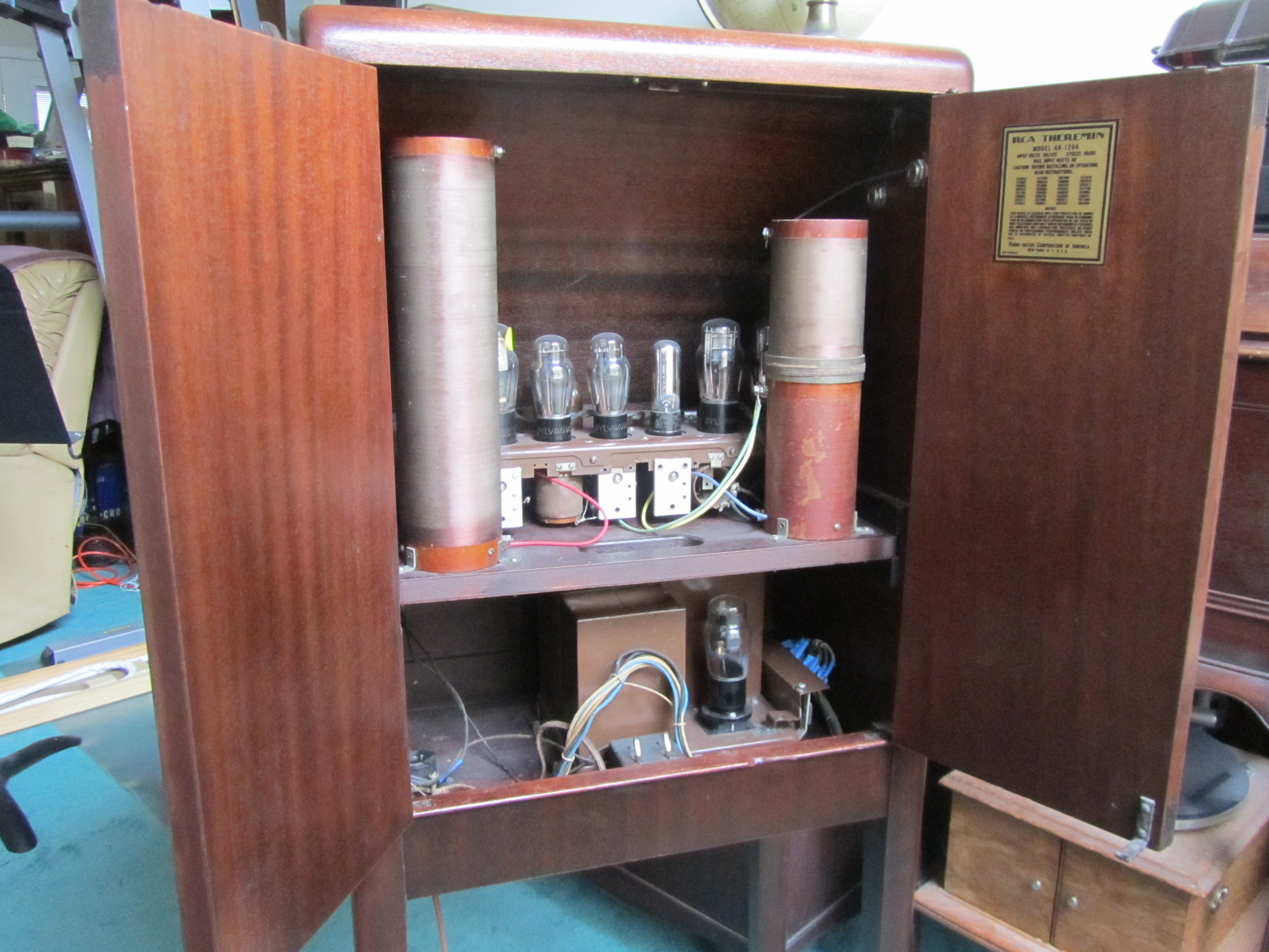
Can anyone can answer why Theremin's pitch EQ coils are so long?
dewster said: "Can anyone can answer why Theremin's pitch EQ coils are so long?"
Now I cannot answer this but would be very curious as to where this can be viewed, schematic and/or photo?
Thanks RS. Any Theremin that uses a parallel tank with series EQ coil is probably "stagger tuned" but I haven't seen evidence that this improves or even affects linearity. An EQ coil can often increase sensitivity though, probably through impedance matching. I believe employing a higher operating frequency will increase sensitivity as well (heterodyned sensitivity that is).

From: Eastleigh, Hampshire, U.K. ................................... Fred Mundell. ................................... Electronics Engineer. (Primarily Analogue) .. CV Synths 1974-1980 .. Theremin developer 2007 to present .. soon to be Developing / Trading as WaveCrafter.com . ...................................
Joined: 12/7/2007
Perhaps the reason for the tall "thin" construction of the antenna EQ coil is/was more a function of mechanics.. as in, a fatter coil takes more horizontal area in the chassis (or, the equivalent of more board area).. As a result, if one has a lot of stuff to pack into this area, and you need to keep components spaced apart to avoid coupling, fatter coils become a problem ?
I think Lev was more constrained by available technology / material than we are, and chose the optimum construction for what was available to him..
I think it likely that the reason why theremins have followed Lev's techniques closely is because no one REALLY bothered to analyse the reasons he did things in the way he did.. Right down at the core, assumptions were made and misunderstandings proclaimed which steered theremin developers down the wrong road.
IMO, this is most clearly seen when one reads detailed descriptions about Lev's front-end.. People have "designed" themins copying aspects like the coil dimensions, using tubes, and attempting to emulate the performance of Levs instruments in this manner - but have used parallel resonant armstrong oscillators and not even noticed that Lev used an entirely different series resonant topology, only loosly based on the Armstrong oscillator.. In all these decades, nobody (at least no one I have heard of) noticed or mentioned how different Lev's oscillators were to what was being used in non-Lev theremins.
Fred.
ps, my experiments with the Lev oscillator have given much better results in terms of stability and (when coupled via a good matched antenna EQ) linearity than I have ever obtained from parallel resonant tank topology.. I do believe this is the secret to the linearity of Lev's instruments - But, for some reason, simulations do not show this.... So until I have removed all doubt from my mind by running extensive repeatable tests, I still could be wrong.
In terms of the sound, other than when close to lock, I do not think the oscillators play much / any part in the output audio - I think the mixer does this job.
From: Eastleigh, Hampshire, U.K. ................................... Fred Mundell. ................................... Electronics Engineer. (Primarily Analogue) .. CV Synths 1974-1980 .. Theremin developer 2007 to present .. soon to be Developing / Trading as WaveCrafter.com . ...................................
Joined: 12/7/2007
"An EQ coil can often increase sensitivity though, probably through impedance matching. I believe employing a higher operating frequency will increase sensitivity as well (heterodyned sensitivity that is)." - Dewster
As I understand it, the reason for the increased sensitivity comes down simply to the transposition of capacitance (the tiny capacitance and change thereof at the antenna) to a much (proportionally) larger change in effective (or "virtual") inductance presented across the tank inductor.
The antenna resonator, when tuned so that it is operating in its inductive region, presents as an inductive reactance - effectively as a variable inductor whos value is determined by the antenna capacitance. One is not changing capacitance across the tank, one is changing the inductance.. So the smaller the (fixed / physical) tank inductance, the greater the effect of the parallel "virtual" / antenna resonator inductance will be on the resulting oscillator frequency.
This is why theremins having a large physical tank inductance and small physical tank capacitance are used best without an antenna resonator (for example the SC / EPE theremins, which operate at 455kHz have tank inductance ou 680uH and tank capacitance of 180pF) - in these cases, the small antenna capacitance is in parrallel with the small tank capacitance, and the changes in antenna capacitance are significant enough to give high sensitivity...
But for theremins operating with a small physical tank inductance (and large tank capacitance) direct connection to the antenna gives (extremely) low sensitivity, because the tiny antenna capacitance is swamped by the large tank capacitance (take the EW with 100uH inductance and 3300pF capacitance, the 10pF antenna capacitance is insignificant) - However, connecting the antenna resonator changes things - the 10pF capacitance is converted to a proportionally much larger change in inductance across the 100uH tank inductance.
The linearizing function is because the "conversion" from capacitance to inductance is non-linear (plot the Xl Xc curves of the antenna resonator against frequency you will find one is linear, the other non linear - and the non linearity acts to convert the square law to an exponential law, resulting in a distance <-> frequency plot which is closer to the required exponential relationship needed for musical linearity)
Fred.
dewster said:
- Say the second winding is open circuited.
- Say you are only able to measure the inductance of the first winding.
This begs the question that if the secondary winding is shorted would it reduce the inductance of the primary and would it cause distortion in an oscillator wave form?
My thought is yes it would.
Christopher
"Perhaps the reason for the tall "thin" construction of the antenna EQ coil is/was more a function of mechanics.. as in, a fatter coil takes more horizontal area in the chassis (or, the equivalent of more board area).. As a result, if one has a lot of stuff to pack into this area, and you need to keep components spaced apart to avoid coupling, fatter coils become a problem ?
I think Lev was more constrained by available technology / material than we are, and chose the optimum construction for what was available to him.." - FredM
I suspect this is it exactly, but feel uncomfortable that I can't come up with any better reasons. If that EQ coil had a transformer winding near the base I'd get it a little more (where the leakage inductance could be doing EQ duty).
Playing around with my coil worksheet, there are diminishing returns with form diameter. Picking 34 AWG single coated magnet wire and a fixed length of wire, inductance seems to max out when the coil height is very roughly equal to the form radius. It's a gentle maxima so a wide range of sizes are nearly optimal, but going super long (as with the RCA EQ coil pictured above) you lose the inductance = turns^2 benefit, so you get higher DCR, lower Q, more laborious winding, etc. Two or more layers would have made sense too (but I suppose with increased self-capacitance and mechanical complexity). <scratches head>
"I think it likely that the reason why theremins have followed Lev's techniques closely is because no one REALLY bothered to analyse the reasons he did things in the way he did.. Right down at the core, assumptions were made and misunderstandings proclaimed which steered theremin developers down the wrong road.
IMO, this is most clearly seen when one reads detailed descriptions about Lev's front-end.. People have "designed" themins copying aspects like the coil dimensions, using tubes, and attempting to emulate the performance of Levs instruments in this manner - but have used parallel resonant armstrong oscillators and not even noticed that Lev used an entirely different series resonant topology, only loosly based on the Armstrong oscillator.. In all these decades, nobody (at least no one I have heard of) noticed or mentioned how different Lev's oscillators were to what was being used in non-Lev theremins.
Fred.
ps, my experiments with the Lev oscillator have given much better results in terms of stability and (when coupled via a good matched antenna EQ) linearity than I have ever obtained from parallel resonant tank topology.. I do believe this is the secret to the linearity of Lev's instruments - But, for some reason, simulations do not show this.... So until I have removed all doubt from my mind by running extensive repeatable tests, I still could be wrong."
This is why I'm super glad that I didn't go the copying route. From a couple of early experiments it was clear to me that a series tank with very large inductor and very small capacitor could produce huge voltages with very little drive voltage. Stick an exceedingly non-critical EQ inductance (of 1x to maybe 10x the tank inductance) on it and both voltage and sensitivity increase somewhat with no associated coupling / tuning headaches. Except for right at the antenna where frequencies are somewhat cramped, basic perceived linearity is almost good enough to not need further compensation (though it can be somewhat improved and more importantly modified to taste via digital post processing). Using a step-up transformer series tank, both with and without EQ, appears to be even more optimal (in simulation - so it's just big talk at this point, I have the stuff on order to start winding soon).
You must be logged in to post a reply. Please log in or register for a new account.