"If that EQ coil had a transformer winding near the base I'd get it a little more (where the leakage inductance could be doing EQ duty)." - Dewster
Correct me if im wrong - but isnt that almost exactly what the "concentrator" coil is? (a seperate coil fitted at the base [inside] of the antenna coil, series connected [perhaps even via a capacitor] with loose coupling to the antenna coil..)
- I cannot remember, will check.. But I am reasonably sure that I saw this on a Lev theremin, probably the RCA.. And the schematic shows a two-coil EQ inductance if I remember correctly - these drawn like they should be coupled ..
Fred.
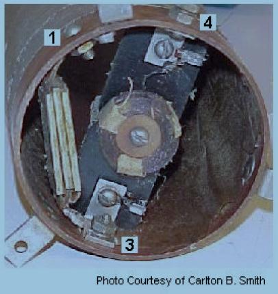
Yep - the RCA schematic does show two inductors constituting the pitch control resonant coil - they are connected with a capacitor, and the coil closest to the oscillator is not visible because it sits inside the lower section of the tall coil.. Its called the concentrator coil - and, as you say, its ideally positioned to make use of the leakage.
So heres yet another area of blindly following without understanding.. Copying the tall thin coils without copying the concentrator coil.. and in so doing losing the advantage of following Levs brilliant engineering, but paying the high price required to do so!
Slowly, layer by layer, I think we are at last starting to understand.. Every little piece, when it clicks into place, is so damn obvious.. Thinking about it, why has so little attention been paid to this concentrator coil? Back in those days a coil like that was no simple off-the-shelf part like a 6300 series inductor - Lev would not have included such a part in the crudest theremin he ever developed if he didnt know it was vital! ... For me, its time to look at every component, and be sure I really understand what every coil and capacitor and resistor and (most difficult) tube REALLY does.