

Thanks Dewster - That bang-bang idea could be better / cheaper.. Take the PD output also to a seperate integrator and derive an error CV.. Really elegant!
Fred.

From: Eastleigh, Hampshire, U.K. ................................... Fred Mundell. ................................... Electronics Engineer. (Primarily Analogue) .. CV Synths 1974-1980 .. Theremin developer 2007 to present .. soon to be Developing / Trading as WaveCrafter.com . ...................................
Joined: 12/7/2007
Thanks Dewster - That bang-bang idea could be better / cheaper.. Take the PD output also to a seperate integrator and derive an error CV.. Really elegant!
Fred.
It probably won't work as drawn. I think at least one integration of the phase error has to happen - in a first order PLL this is the phase / frequency thing in the VCO, where frequency is the input with phase as the output. But I think it might work if a real PLL (phase detector + LPF + VCO) was in there somehow, or if a delay locked loop were somehow employed (a miracle occurs here).
From: Eastleigh, Hampshire, U.K. ................................... Fred Mundell. ................................... Electronics Engineer. (Primarily Analogue) .. CV Synths 1974-1980 .. Theremin developer 2007 to present .. soon to be Developing / Trading as WaveCrafter.com . ...................................
Joined: 12/7/2007
"The LPF thing was speculation on my part, evidently not good speculation!" - Dewster
Please dont make the assumption that what I have seen, or more important perhaps how I have interpreted what I have seen, is correct - I make a lot of mistakes, and the frequency analysis I ran was far from elegant! Your speculation may still be good.
"It probably won't work as drawn." - Dewster
Yeah - But thats no problem.. The concept is interesting... Also, it should be reasonably simple to simulate and get right.. Once one has it running in the simulation, it should be easy to alter the antenna capacitance and hone the design for optimal behaviour.. Its not like variable frequency stuff involving parallel and series resonators, where every simulation takes hours.
The switch will need some thinking about - one beauty of opto isolators is, well, the isolation ;-) .. The signal across the switch will be AC, so standard 4066 or the like will need some fiddling (actually, probably not usable), also, the H11F1 can have up to 30V across it (as in, +30V / -30V, 60V P-P) and its going to perhaps be a bit tough to get that easily any other simple way - perhaps two fast transistor optos, one for +Ve 1/2 cycles, one for -ve.
I may just stay with the lossy original design though - The switched scheme looks great for the PLL, but the (modified) error signal needs to drive a HF oscillator which isnt in a loop, so I will need a purely voltage controlled oscillator - and its probably best for both oscillators to be as nearly identical as possible, so ..
>> But one really nice thing about your idea, Dewster, is that the switching scheme isn subject to component variations the way the H11F1 is - They are really hugely different part-part in terms of resistance vs photo current - and the LED's do degrade over time which changes the LED current <-> FET resistance relationship.. For an analogue control scheme requiring the precision for theremin application (which is far more severe than most applications where one can get away with minor change over time), the H11F1's would probably need a month of continuous heavy "cooking" before they were put into the boards..
It may just be that a simple varicap tuning scheme would be best - I hate them, but once you get it right they do work reliably.. but it does involve generating some higher voltages to bias them when they are acting on the kinds of levels present..
Just for anyone not understanding, heres a picture which may make it easier to understand my idea:
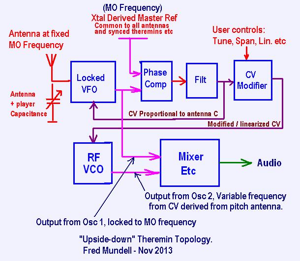
The upper section (leave out RF VCO and mixer) could be duplicated and the modified CV taken to a VCA to implement a volume antenna, also running at MO frequency.. And one can have as many antennas as one wants for whatever one wants to do.. and they wont interfere with each other (or at least not in any assynchronous way) - but your hands probably will if the antennas are too close together! ;-) ... This is the problem with an idea like the above, its easy to get carried away and forget our physical limitations!
Fred.
From: Eastleigh, Hampshire, U.K. ................................... Fred Mundell. ................................... Electronics Engineer. (Primarily Analogue) .. CV Synths 1974-1980 .. Theremin developer 2007 to present .. soon to be Developing / Trading as WaveCrafter.com . ...................................
Joined: 12/7/2007
Just to extend this hijack a bit, LOL ;-)
The question of electronic tuning has been a continuous issue - its absurd, but an ideal solution for theremins just hasnt turned up yet (or at least I havent found it) - No big problem if one is tuning an oscillator with a small tank inductance, where there are all sorts of solutions - but tuning at the antenna side, where there are high voltages and more critical constraints, has been a bother.. The reactor scheme works well, but its expensive, takes ages, and hasnt given enough in the way of reliability or repeatability for me to run with it (apart from which, its probably too slow to work in my present design).
Looking at using varicaps, the problem is the required bias voltages in order to have any significance against the large signal voltages --- Now it may well be that I am re-inventing the wheel - RF design is not something I ever did before I got into these damn theremins.. In fact, I avoided everything involving inductors and RF like the plague...
I have just found some photovoltaic optos meant for driving MOSFETs, these consist of an array of series photodiodes driven by a LED, and output a voltage proportional to LED current.. Alas, most, due to their intended application, have fast turn-off circuitry which makes them useless for what I want to do - but they output about 8.5V @ 15uA for a 10mA LED current..
If I could find some without any shut-down or other circuitry, where I could get an isolated voltage proportional to LED current, use a couple to get say 20V controllable by the LED current, and strap this across a reverse biased diode (varicap) AC coupled to a bridge rectifier, then it could be a great current controlled tuning capacitor..
Theres loads of frustratingly tempting ideal solutions on view - from MEMS capacitors to capacitors using Ferroelectric dielectrics, with ideal charactaristics, but trying to find anywhere one can actually get these parts is another story - they seem to all be costom manufactured for mobile phones or defense, and no-one is selling them :-(
I might actually need to go back to a conventional parallel oscillator just to simplify the tuning .. Thinking about it, my main reason for antenna-side tuning was to maintain the linearity achieved from the antenna resonator - But as this scheme overcomes that issue completely, perhaps theres no rationale in sticking with this far more difficult tuning node.
Fred.
"I might actually need to go back to a conventional parallel oscillator just to simplify the tuning" - FredM
One thought: Theremin pitch oscillator operational range is fairly narrow, you might be able to adequately "tune" it by playing with the phase delay (RC) network rather than the resonant tap capacitance.
The nice thing about series / capless / tankless is there aren't two fixed tunings (tank LC and EQ L | Antenna C) at odds with each other, needing special care at the factory, and retuning should the environment / antenna geometry change. The constraint of a fixed frequency at the antenna (which is admittedly so gorgeous I want to marry it) is dragging you back to onerous EQ network tuning. If you could relax the fixed antenna frequency requirement then all the icky tuning issues go away.
From: Eastleigh, Hampshire, U.K. ................................... Fred Mundell. ................................... Electronics Engineer. (Primarily Analogue) .. CV Synths 1974-1980 .. Theremin developer 2007 to present .. soon to be Developing / Trading as WaveCrafter.com . ...................................
Joined: 12/7/2007
"The nice thing about series / capless / tankless is there aren't two fixed tunings (tank LC and EQ L | Antenna C) at odds with each other, needing special care at the factory, and retuning should the environment / antenna geometry change." - Dewster
Oh, I absolutely agree! - Whatever I end up using, I really want it to have a single resonator.. IMO, the dual resonator scheme brings great benefits, but if one doesnt need the main benefit (linearity improvement) as that is being done elsewhere, then its trouble vs benefit ratio increases .. If I can get the other main benefit (higher antenna voltage) through other means, then thats the way to go.. (the benefit I cannot get without an antenna inductor is the 'relocation' of the sensitivity to the antenna, away fron the oscillator - but thats no real loss - just requires more care on the layout)
By far the simplest electronic tuning is by varying the DC current through the tank inductor - I have single transistor oscillators with untapped inductor (the simplest possible configuration) that are stable and would do the job - Increase the supply voltage a bit, and its easy to get about 50V P-P on the antenna, which is about what I deem as an acceptable minimum... Then there are a number of other tuning schemes using variation of capacitance on semiconductor parts (through Miller effect etc) which are also simple.
My "upside down" topology really requires a complete re-think of all the usual theremin front-end issues - For example, the issue of sensitivity.. With conventional theremins, one needs a frequency deviation on the pitch oscillator which equates to the audio span (number of octaves) you require.. The "upside down" doesnt need this, as the error voltage can be amplified as required... My first thoughts were that going for as big a deviation as possible (when the oscillator locking was disabled) would produce the greatest SNR, and I am still inclined to think this - But I wonder if this is actually correct.. Would perhaps having less deviation result in more stability, and subsequent amplification of the resulting error CV and the post-processing / filtering of this (I could have a 500Hz LPF on the CV and still have less than 5ms latency) result in better SNR ?
I am also looking (at least to start with) at a simple low cost version of this theremin - perhaps based on my SkyWave (S/C oscillators) as the only real problem with this design was the Tank-EQ stuff - If one accepts the poor linearity when no linearization (antenna-side inductor) is fitted, and just has antenna capacitance in parallel with the tank capacitance, the oscillators behave well and are easy to tune and quite stable - its only when (as with the EPE-2008 and other variants which tacked an antenna resonator onto this design, which is ,IMHO, unsuitable for antenna equalization) that problems occur.
But whatever - theres dozens of possible oscillators that could do the job, and be easily tuned - I prefer the idea of series resonant, but this does remove the easiest tuning option - that of controlling DC current through the inductor.. Also, other electronic control of capacitance through reverse biasing or miller etc, are difficult / impossible to implement, as the only node one can 'tap' is directly at the (HV) antenna, leaving the main option a small saturable reactor in series with the tank inductor - its reasonably easy and not hugely expensive (about £5 total when one includes the needed choking inductors), but its still an extra £5 (cost) per oscillator (3) - not easily absorbed in a low cost theremin, fine for mid - high end.. but the H11F1 is cheaper -
Been trying to squeeze too many conflicting things into this design I think - I wanted a low voltage internal supply (<9V, certainly <12V) to enable powering from a simple wall-wart or battery without fuss, wanted good antenna voltage, and all the other essential - Perhaps I need to get realistic and go for + 15V /- 15V supply which makes getting all the other things a lot easier!
Fred.
"you might be able to adequately "tune" it by playing with the phase delay (RC) network rather than the resonant tap capacitance." - Dewster
I did mess with this earlier, and the simulation showed no change in frequency (which at the time I was pleased about - it only affected amplitude) - but I will play with it some more..
I suppose you could just drive it and look at the phase deviation, with no attempt to tune anything. That might actually give you some linearity improvement near the antenna if you placed the resonance peak so that the phase deviation is pooping out there. The issue that I've seen with this is bad things happen to the thresholded detection when you grab hold of the antenna, so simple overdrive of a CMOS gate for this function is perhaps out?
Environmentally the pitch and volume antennas might then just need a global adjustment, something you could do by varying the frequency drive to both. I suppose this would put the kibosh on multiple Theremins playing closely together, but I wonder if you might get weird slow phase effects doing that even if all of their references are crystals?
I haven't done anything with the volume side yet (too busy designing the equivalent of a solar powered picture straightener) and am somewhat dreading the interactive "fun" that is likely in store.
In terms of SNR, this is where I've been for the last year+ and it's no fun. When I was still in school I could run to one of the communications profs to solve these kinds of things for me in 5 minutes. When I lowered the series tank to below 10pF I saw the expected increased sensitivity as well as some increased instability, and it's hard to know where the happy medium is.
From: Eastleigh, Hampshire, U.K. ................................... Fred Mundell. ................................... Electronics Engineer. (Primarily Analogue) .. CV Synths 1974-1980 .. Theremin developer 2007 to present .. soon to be Developing / Trading as WaveCrafter.com . ...................................
Joined: 12/7/2007
"I wonder if you might get weird slow phase effects doing that even if all of their references are crystals?" - Dewster
My plan was to use a PSoC with a 32kHz crystal, it has an in-built PLL which multiplies this up to 48MHz (well, 24MHz, but there is a doubler one can use).. Divide this down to my required MO Frequency..
There would be a patching arrangement - A 32kHz output socket, and a 32kHz input socket.. The "Master" theremin's (buffered) 32kHz (derived from its crystal - well, actually derived from dividing the 24MHz down by the same divisor as the PLL has) would be connected to the input socket of the next theremin - which would use this instead of its local 32kHz crystal, and provide a 32kHz output to the next theremin... (should just add that any theremin could act as a "master" or a "slave - the only constraint being that one doesnt plug any sync into the input of the "master" )
This way, everything should stay perfectly synchronous..
No real need to use a PSoC - but it has everything to do the job in a 8 pin DIL .. Or I might go for a 28 pin part (only a extra couple of £) and implement a mixed signal register switching voice, or a pitch to voltage, or whatever.. If I go to a PSoC 3 or 4, I can implement some really fancy phase detectors in their PLD's ... Here I go again, LOL ;-)
I may, of course, need to implement a seperate analogue PLL if the DPLL in the PSoC doesnt behave well in this application - But my past experiments indicate that it should be fine..
You are certainly right that individual Xtal oscillators wouldnt work - the frequency deviations could be well into the audio range, not only would you get 'phasing' effects, you'd probably get ghost tones all over the place! ;-) .. This is one area I am a bit concerned about - One would need to adjust the tuning for theremins recieving the sync signal, as it will be different to the frequency of the MO they are usually tuned to, so the phase voltage will shift by this error.. This means that my frequency control circuit must have wide enough span to cater for the worst case Xtal variation of other theremins.. I havent done the sums yet, but I think that if the 32kHz oscillators are carefully trimmed to their 32.768kHz reference, it should be ok (and only minimal re-tuning, if any, would be needed when slaving them) - .. Absolutely no problems though for any antennas sharing the same MO in the same theremin.
The other method I thought about was having a seperate MO "Transmitter' which radiated a MO at say 4* the theremins MO frequency - This could be picked up by every theremin in the vicinity - but it doesnt really solve anything, because each theremin would need a transmitter (when playing alone), and when they share a common transmitter, differences between the frequencies of these transmitters would pose the same problem .. And this scheme would be a lot more expensive!
Fred.
From: Eastleigh, Hampshire, U.K. ................................... Fred Mundell. ................................... Electronics Engineer. (Primarily Analogue) .. CV Synths 1974-1980 .. Theremin developer 2007 to present .. soon to be Developing / Trading as WaveCrafter.com . ...................................
Joined: 12/7/2007
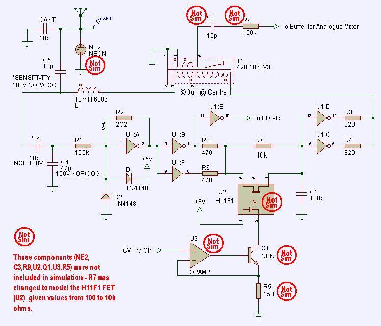
And this is a series resonant oscillator, based on your topology and ideas Dewster, which seems (on simulation) to do everything I need.. ;-)
Many thanks!
Fred.
The value of C5 determines the antenna sensitivity (kHz/pF) and also the amplitude on the antenna - With it shorted, this amplitude is about 160V p-p, and sensitivity is about 4.5kHz/pF, with it at 10pF, both of these values are about halved with given antenna capacitance (2.09kHz/pF) / 80V p-p . Varying the H11F1 resistor (R7) from 100R to 10k give a frequency change of about 4.1kHz - Increasing this R to >15k causes oscillator instability, so (hopefully) 10k with 100pF will be a safe maximum.. These values will I expect be determined by the operating frequency, so may need changing if this is changed.. I havent done any calculations on this, I just played with the values in the sim.
Oh yes - As shown, Operating frequency ranges from 354.7k to 360.6k (combining the CV tuning and antenna capacitance changing from 11pF to 10pF) - taken before I added the 42IF106
I would like to increase the CV span, but its one of these things one can sweat over in simulation and then find that the board behaves completely differently, Simulation is often far more critical than real life.. I will need to increase the span for the 'slave' oscillators - but its not absolutely critical, because I could use parallel resonant oscillators for the 'slaves' (RF VCO's) as they dont need a high antenna voltage (have no antenna) .. Will probably do this anyway, as its a lot simpler and cheaper - I can implement any thermal compensation on the CV.
It would be great if anything here is of use for your digital theremin - as ive hogged this page and hijacked your thread ;-).
>> Final update today.. Reducing R6 and R8 to 120R expands the CV tuning range to >6kHz .. Whatever I do, this seems to be the limit of tuning I can achieve before I get too close to instability - I have changed the delay topology, put two RC's in, but I come up with a top figure of 6.22k ... Which is enough if it works in practice! ... Now I need to study the 'design' of this phase shift / delay network and try to fully understand it ;-) .. the circuit below with R6 and R8 @ 120R is as good as I can get.
-
Fred (I'm spit-balling without a net, there be crazy talk here):
The voltage boost (HV swing) and narrowness of the resonance peak in any series LC circuit is directly proportional to Q. If you lowered the Q of the tank (with a fixed damping resistance in parallel with either / both the L or C) you could widen the resonance peak. Make up for the swing reduction with more drive current. Though you would lose some rejection of environmental interferers.
Since you are driving the antenna directly with a fixed frequency, you don't need any kind of feedback other than phase information to tune the tank L or C. If you go tankless you can only change the L. It would be nice if you could change the L linearly, so as to use the error as an output. I wonder if you could use high speed PWM to switch in / out a small section of winding in a tankless design? Or variably saturate the 6300 with another winding?
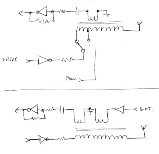
Something tells me I may be forced down this path due to volume / pitch side interactions, and that it won't be pretty.
You must be logged in to post a reply. Please log in or register for a new account.
