Let's Design and Build a (mostly) Digital Theremin!

Posted: 12/5/2013 9:16:30 PM
dewster

From: Northern NJ, USA

Joined: 2/17/2012

"Applying PWM for tuning is nothing other than FSK modulation where the modulating frequency is above the modulated frequency. Mr. Fourier and Mr. Laplace confirm that it will give weird results..."  - Thierry

The question though is "modulation of what?"  Resonant structures often recirculate large energies, tend to keep resonating once started, and can't quickly change or stop on a dime.

Posted: 12/5/2013 10:01:50 PM
FredM

From: Eastleigh, Hampshire, U.K. ................................... Fred Mundell. ................................... Electronics Engineer. (Primarily Analogue) .. CV Synths 1974-1980 .. Theremin developer 2007 to present .. soon to be Developing / Trading as WaveCrafter.com . ...................................

Joined: 12/7/2007

I dont know how to reference what the simulations show against Fourier or Laplace, or do the maths by hand that the simulation is effectively doing, unseen, for me..

All I know is what I see - and it makes sense at a visual / intuitive level.

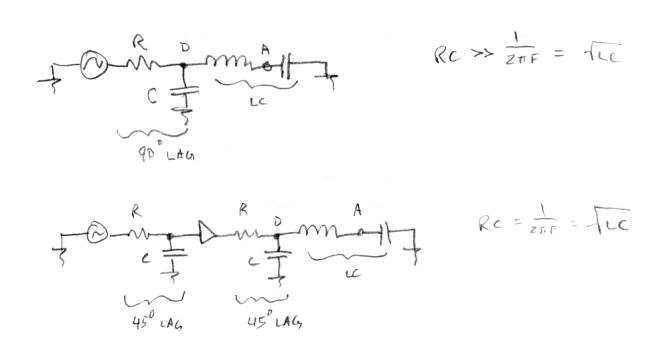
If I operate the PWM over a complete cycle (as in, PWM frequency = MO frequency) there are weird results (dont forget, with the PWM high I am effectively reducing the C in series with the L) - at 50:50, the resulting distortion of the waveform is most extreme (0ne half cycle is operating at the extreme difference in C to the other 1/2 cycle) - The distortion reduces as the PW increases or decreases from 50% - to me it makes sense.. oh, it does "control" the frequency - lowest frequency is when the PWM is low, highest when its high)

If I operate the PWM at twice the MO frequency, each 1/2 cycle sees the same agregated (switched) capacitance in series with the L for each 1/2 cycle, and at the the antenna there is little distortion.

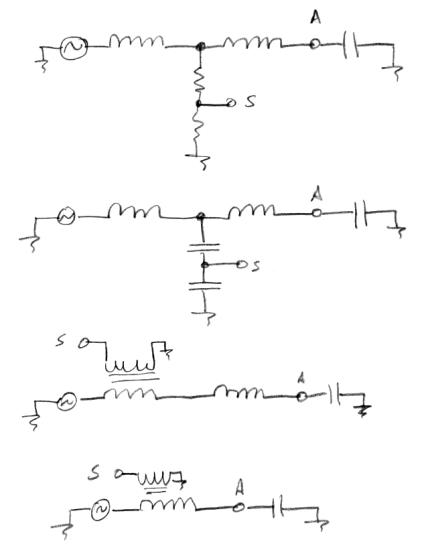
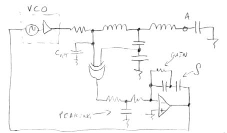
As the C which is being switched (effectively shorted when the PWM is high) is at the drive side, the voltage across it at any time is low - With my latest simulations I have the drive directly coupled to this switched C, followed by a couple of clamping diodes, followed by a 220R resistor, followed by the inductor, followed by a capacitor to ground (the antenna) - and it all seems to behave - I can change the frequency by changing the PWM (using a simple SQW/Pulse SPICE generator component), and distortion is not excessive.

But I havent done extensive examinations, havent run full FFT on the antenna waveforms for any but a few spot checks - I am busy trying to get the loop to work - I have this running a bit, but have devised a somewhat strange frequency / phase detector and rather special PWM circuit - I was too ambitious, should have started simple and expanded - but I only ran one extremely crude PLL simulation, never took enough tests, before I made thing complicated -- If I dont have a breakthrough soon I will need to go back to the earlier PLL simulation and work up from there..

Fred.

* I have needed to adjust the simulation to avoid convergence errors - it only works quite close to setting beyond which I do not trust the results -  just within believable parameter boundaries, but not with the accuracy that gives me a lot of confidence.

Posted: 12/5/2013 10:56:06 PM
dewster

From: Northern NJ, USA

Joined: 2/17/2012

More LC notes:

Concentrating now on the series LC, how can we deal with the 90 degree phase lag between the drive and the oscillations?  One way is to use RC lag elements.  What's great about doing this is we can use a drive source which contains lots of harmonics (like a square wave) and kill most of the harmonics with the RC construct, because it is a natural first order low pass filter.

At top is a single RC giving almost all of the 90 degree lag we need.  The problem with this circuit is the extreme attenuation the RC imposes, the not-quite 90 degree lag we get from it, and a fairly touchy frequency dependent attenuation.

At bottom we are using two RC networks in series with a buffer between them.  The attenuation is less here, but still frequency dependent, which could be an issue for some applications.

Posted: 12/5/2013 11:06:12 PM
Thierry

From: Colmar, France

Joined: 12/31/2007

In ever case the PWM frequency would have to be synced with the MO frequency, so that there would always be an entire multiple of PWM cycles during one MO cycle to prevent jitter (shorter and longer periods of the MO).

Going the Fourier, Laplace or any other mathematical way will not bring you much new insight, I just scribbled a few lines with a pencil on the border of a newspaper, taking the PWMed MO signal by sections as two solutions of the second degree differential equation, alternating with the PWM on-off to get a rather intuitive first view on what will happen. Theoretically it can work and it will for sure in practice when you take my conclusions of the first paragraph into account.

The waveforms at the antenna may look weird, but IMHO that doesn't matter for the loop, it will perhaps just require an additional LC or other resonant filtering before going into heterodyning. The most important seems to me that you feed the phase comparator with a MO signal with a constant 50% duty cycle which requires the PWM frequency to be an even multiple (2,4,6,...) of the MO frequency.

Dewster mentioned the 90° phase lag of the LC series resonant circuit. Why should it be compensated by RC elements? XOR or quadrature based phase comparators work best with a 90° phase lag.

Posted: 12/5/2013 11:21:08 PM
dewster

From: Northern NJ, USA

Joined: 2/17/2012

More LC notes:

How can we sense the series LC resonance without loading it down to much?  We don't want to significantly lower the Q (our I/O voltage amplification factor) by introducing "rust" into the works, or remove too much energy in the process of observing.  Above are some schemes I've experimented with.

At top is a split inductor (either coupled or not) with a resistive divider.  The split needs to be significantly into the windings so the resonant swing swamps the drive waveform.  Any capacitive loading of S can be a problem.

Next is a resonant capacitive voltage divider.  The top capacitor should be on the order of the tank capacitance, the bottom capacitance much larger to give significant voltage division.  This works great but requires a ~center tap or second expensive inductor, and is pretty sensitive but not 100% optimal due to the capacitive loading.

We're really interested in sensing the current circulating in the LC inductor.  The next circuit does this with a transformer in series with the LC.

Finally, it is possible to combine the sense transformer and the LC inductor by just using a winding on the LC inductor.  The sense winding doesn't need to be very tightly coupled, in fact light coupling can help unload the sensing.  This in essence is my "tankless" design, where the inductor normally thought of as the "EQ" inductor is stimulated directly with a non-resonant drive.  It nears the theoretical maximum in terms of sensitivity, but doesn't attenuate drive harmonics (at the sense point) very well.

Posted: 12/5/2013 11:37:24 PM
FredM

From: Eastleigh, Hampshire, U.K. ................................... Fred Mundell. ................................... Electronics Engineer. (Primarily Analogue) .. CV Synths 1974-1980 .. Theremin developer 2007 to present .. soon to be Developing / Trading as WaveCrafter.com . ...................................

Joined: 12/7/2007

Thierry:

"The waveforms at the antenna may look weird, but IMHO that doesn't matter for the loop, it will perhaps just require an additional LC or other resonant filtering before going into heterodyning."

Agreed - I think the distortion wont be a problem in this respect.. But I dont like distorted antenna waveforms from an emission perspective.

(actually, the antenna connected oscillator wont probably  be used for heterodyning, - I intend to take the clean MO frequency into a LC filter and produce a sine from this to use for heterodyning (its one simple IFT extra, and eliminates all sorts of potential problems ) - the antenna oscillators sole function is deriving a CV to drive the "mirrored" VFO... The "mirrored" VFO is not in a loop and doesnt need to cater for the large tuning span that the antenna oscillator potentially must deal with - it only needs to go from MO to MO + or - 16kHz - even 9kHz would give more octaves than could be sensibly squeezed into 60cm.. Adequate filtering (say 500Hz ) on the CV of this "mirror" VFO should get rid of most (hopefully all) noise and jitter and whatever that the PLL may throw up..

"The most important seems to me that you feed the phase comparator with a MO signal with a constant 50% duty cycle which requires the PWM frequency to be an even multiple (2,4,6,...) of the MO frequency."

Yes - keeping the capacitance balance on each 1/2 cycle (2*MO PWM frequency) seems to work even with other than 50:50 duty cycle - If one must stay with 50:50 then its not a PWM! - But I think what you meant was that the PWM frequency must be equal in both 1/2 cycle - ie, 2, 4, 6 * MO.

Due to what I am trying to do (generate a modifyable 'ramp' waveform at 2*MO or perhaps 4*MO at worst case, in which is "embedded" the adjustable linearity correction, and feed this ramp to a comparator which produces PWM in response to the PD error voltage applied to its other input) I must use as low a frequency as possible - so PWM @ 2*MO (or perhaps 4*MO at worst case,).. If this doesnt work, then some other tuning scheme will need to be employed.. It might be just as simple as driving a couple of Varicaps placed where my switched capacitor is at present (with, of course, the required decoupling / biasing etc)

Fred

Posted: 12/6/2013 12:14:25 AM
Thierry

From: Colmar, France

Joined: 12/31/2007

"But I think what you meant was that the PWM frequency must be equal in both 1/2 cycle - ie, 2, 4, 6 * MO." - Fred

Yes. And I found that most distortion and other problems will most probably be caused by the transient currents in the moment when the additional capacitor is switched on. I concluded that the "pulse" part of the PWM should by symmetric on the time axis around the zero crossings of the MO signal, so that the additional capacitor is switched "on" when the MO signal has the same voltage as it had when the capacitor was switched "off" which will greatly reduce the transient loading current. See my scribble below where the grey lines indicate the points of identical MO signal voltage.

Posted: 12/6/2013 12:19:38 AM
dewster

From: Northern NJ, USA

Joined: 2/17/2012

More LC notes:

Can we somehow exploit the 90 degree drive / sense difference?  Yes, with a PLL that uses an XOR phase detector.  Above shows the resonant capacitive divider sensing scheme (the one I have most practical experience with) with an XOR phase detector comparing the LC drive and swing.  Following this is a standard LPF / integrating PLL loop filter.  The XOR PWM is filtered down to roughly DC (little ripple), then given a controlled amount of gain and integrated by the op amp.  Since the op amp + input is referenced to ground, the PLL will endeavor to maintain 50/50 duty cycle from the XOR input.  The output of the loop filter feeds a VCO.  Copt may be used to reduce drive harmonics.

My implementations of this use digital versions of the phase detector, loop filter, and VCO, but that's essentially it.  Examining the digital "charge" on the integrator gives the operating point (frequency).

Posted: 12/6/2013 12:48:47 AM
FredM

From: Eastleigh, Hampshire, U.K. ................................... Fred Mundell. ................................... Electronics Engineer. (Primarily Analogue) .. CV Synths 1974-1980 .. Theremin developer 2007 to present .. soon to be Developing / Trading as WaveCrafter.com . ...................................

Joined: 12/7/2007

Hi Dewster,

Thats a neat configuration! All thats needs to be added I think is some series R's on the XOR legs, and perhaps a pull-down on one?

I am being completely pedantic here, sorry.. I know its just a concept sketch, and for that its great  - but for the benefit of others who may look at the schematic above..

In reality, you cannot drive an input to a logic gate as shown - One XOR input is connected to 2 capacitors, with no DC (resistive) path to either +V or 0V (Gnd). It should also be realised that if the voltage on the XOR input is swinging below GND, it will reverse bias this parts protection diode shorting the -ve 1/2 cycle to ground, and possibly damaging the part.

Likewise, the other input to the XOR has the potential for exposure to off-limit voltages.

This is the kind of stuff we take for granted, and among ourselves exchange these sort of sketches.. But I can just see it - some hobbyist trying to build it resulting in some engineer on some forum somewhere wasting hours -

;-)


"I concluded that the "pulse" part of the PWM should by symmetric on the time axis around the zero crossings of the MO" - Thierry

Interesting observation Thierry - Thanks. - I will play more with this when I extracate myself from this place for a while ;-) But it certainly looks like sound thinking... Which is a shame, because its a lot more difficult to implement.**

Fred.

Added:

**Ohhh - Actually, its not! Its easier to implement! I just substitute the MO*2 Ramp for a MO*1 Triangle!!! ;-)

Posted: 12/6/2013 3:53:48 AM
dewster

From: Northern NJ, USA

Joined: 2/17/2012

"In reality, you cannot drive an input to a logic gate as shown - One XOR input is connected to 2 capacitors, with no DC (resistive) path to either +V or 0V (Gnd). It should also be realised that if the voltage on the XOR input is swinging below GND, it will reverse bias this parts protection diode shorting the -ve 1/2 cycle to ground, and possibly damaging the part." - FredM

Yes, I should warn anyone not to actually use this, it's more for concept than anything else, though with proper DC bias and protection it could work.  And particularly without proper loop stability analysis the PLL probably won't function well, if at all.  I have a spreadsheet that can help along these lines, there are many variables to consider.  For my DPLL I similarly rely on stability analysis, though it is a bit simpler.

"But I can just see it - some hobbyist trying to build it resulting in some engineer on some forum somewhere wasting hours" 

That would be you starring in the latter role! ;-)

You must be logged in to post a reply. Please log in or register for a new account.