Let's Design and Build a (mostly) Digital Theremin!

Posted: 1/28/2014 11:58:52 PM
dewster

From: Northern NJ, USA

Joined: 2/17/2012

Hive Excel Simulation

I started this over three months ago, worked on it pretty intensely for over a month, then sporadically until today.  Only lately has it started to pay off:

http://www.mediafire.com/view/bnh9io5tvdjwct7/HIVE_SIM_2014-01-28.xls

It's a simulation of a single thread in Hive (there are 8 threads and they are all identical, with 8 independent stacks and one interrupt each, and with equal access to the same memory space).  I haven't exhaustively tested it, but it runs my division/mod, square root, log2, and exp2 subroutines fine.  It even helped me discover a pop typo in one of them (which generated a stack fault).  So I'll be using it to develop and test my processor subroutine code as it gives a fair amount of visibility into what is going on. 

There aren't any options to import or export code yet (I need to get some SPI EEPROM or FLASH on the demo board and get uploading working - recompiling the entire FPGA to merely change a bit of boot code gets kind of tedious kind of fast).  Not feeling a ton of pressure to do this though, typing code is is pretty quick, certainly faster than setting toggle switches on an Altair 8800!  And manual code export via text search & replace should be fairly trivial.

Posted: 1/29/2014 12:37:29 AM
FredM

From: Eastleigh, Hampshire, U.K. ................................... Fred Mundell. ................................... Electronics Engineer. (Primarily Analogue) .. CV Synths 1974-1980 .. Theremin developer 2007 to present .. soon to be Developing / Trading as WaveCrafter.com . ...................................

Joined: 12/7/2007

Dewster - I am real interested! - But im not going to load up the spread sheet just yet, am having a brain distraction overload!

One of the things I need to finalize soon is how I implement my exponential conversion (for outputting 1V/Octave and my On-Key analysis / emphasis) - I have a fully analogue system, but this is an area where I think digital may win hands down - certainly from a cost / fiddle factor perspective.. I dont really need analogue for this function, as it only drives external synths, and OKE only drives amplitude variation.. I will certainly be turning to you for help / collaboration on this!

I am starting to wonder whether there is any possibility of getting a hybrid modular specification together - a specification that could allow developers to build compatible modules which could be either heterodyning / analogue or digital or both.. I think perhaps the theremini may be something of a "wake up call" for us - "We" are taking too long because "we" arent collaborating and are perhaps holding too tightly to our individual narrow perspectives.

It seems to me there are about 5 "public" developers who are active - Only two are actually producing anything (and one of these isnt really "public" and doesnt disclose his designs) - There are things some people want which others dont, and topologies some people hate that others couldnt give a sh*t about.. Things like latency and linearity that would make an instrument unacceptable to some, but others wouldnt even notice.. It just seems to me that a bunch of compatible modules which could be linked together to produce bespoke instruments could be a good deal for everyone -

Even down to the most basic level - drift for example - if one had compatible front-end modules, one could supply a cheap low spec module using simple ferrite inductor, or one could supply a high-end module with a honking air coil.. Someone may not care about drift but want a wavetable voice with pitch correction, others may want a good front end with E-Pro like register switching and sounds, caring not how these sounds are produced...

Yeah - the mass market will no doubt opt for the theremini, LOL ;-) But we could, I think, nibble into that market a bit - and share the whole "real theremin" market.

Its probably an impossible dream - and much as it would be nice to have an "open" project, I think the managment of such a diverse project would sop all the time of those who are actually capable of producing useful contributions - I would like a "open" project in the sense that everyone could see it, but "closed" in the sense that only competent persons could participate in it.

"we" could even run an ebay shop where modules / boards / components could be sold - a co-operative type theremin store - There is no point in doing anything if people of whatever skill level cannot buy it - those capable of DIY could buy kits / modules, but builders could also buy or join the co-op and sell ready made instruments based on the modules, in the store, adding their markup.. In fact, this could work even if not all modules were compatible..

Im a bit loath to hijack your thread again ;-) .. If this goes anywhere then a shift to a new topic will be needed - please feel free to copy this to a new thread if you wish - I will then delete this post.

Fred.

Posted: 1/29/2014 4:42:54 PM
dewster

From: Northern NJ, USA

Joined: 2/17/2012

Fred,

You bring up some interesting points.  Not trying to poo-poo the idea of modular or discourage your thoughts along these lines, but likely 90% of my design functionality will be inside an FPGA, so a modular approach can't go but so far.  AFE, tuner display, UI controls and display, and some form of DAC will be off-board though, and I suppose these could be offered to others via PWB layouts.

I think an air core on the pitch side is pretty much mandatory if one goes with digital heterodyning (just started looking into this) so helping someone else do it with an inferior coil doesn't seem like time all that well spent. 

For me the biggest sticking point at the moment is physical design.  But this seems to be an issue all around for DIY Theremins including the Open.Theremin.  Having a kit or list of parts is kind of incomplete without the all important enclosure.  Separating the warm electronics from the pitch coil seems like a good goal.  Sufficiently separating the pitch antenna from the volume antenna seems like another. ;-)

I think we really are collaborating here, and even if it doesn't produce one design that embodies all of our ideas, whatever multiple offerings may someday see the light of day will likely employ much of the same set of reasoning at their basis.

Eric

Posted: 1/29/2014 10:49:49 PM
FredM

From: Eastleigh, Hampshire, U.K. ................................... Fred Mundell. ................................... Electronics Engineer. (Primarily Analogue) .. CV Synths 1974-1980 .. Theremin developer 2007 to present .. soon to be Developing / Trading as WaveCrafter.com . ...................................

Joined: 12/7/2007

"For me the biggest sticking point at the moment is physical design.  But this seems to be an issue all around for DIY Theremins including the Open.Theremin.  Having a kit or list of parts is kind of incomplete without the all important enclosure. " - Dewster

You are FAR from alone with this "problem" .. But even this is the sort of thing that a co-op store could "enable".. There must be many people with better skills in this area than folks like you and I who have invested far more of our time and passion into electronics than into crafting enclosures!

It has actually surprised me that noboby has a small cottage industry producing both cheap "boxes" and "high end" boxes for theremin (and synth) DIY'ers - The mass market enclosures are too small (short on length particularly) for keyboards and theremins.. Also, sloping panel enclosures of any kind are quite few - particularly long ones, or ones with a flat top!

My thinking is shifting more towards the "co-op online theremin store" than to a online "collaboration" or "project" - Somewhere that sellers and buyers of theremin bits can go to display their products / parts, can collaborate with other suppliers to put kits together, and where buyers can shop for what they need or want at any level -  Want an air coil for an RCA? someone here has one for sale or can build one for you  - Want an IFT?, its here - Want an EW or theremini?, its here - Want a Wavefront style cabinet for your Jaycar theremin? - Someone here can build one for you... Want a complete assembled ant configured Dewster Digital or FredM Analogue, with warranty ? - Available (on a 3 year lead time LOL ;0)

IMO, its the distribution of cost / risk that makes this idea appealing - We could be building boards and selling them - Someone could be building suitable cabinets and selling them - I can lay out the money for say 100 boards, but not for 100 baords and cabinets - they can lay out the money for 100 cabinets but not for these and 100 boards...

Customers could buy our boards and the cabinet, and we (or other builders) could quote for assembled versions based on stuff bought from our store (or we could have fixed lower price for predefined configurations ).. One order and the customer could have exactly what they want, and all the individual sellers (of parts or services)involved would get business. 

Each of us is free to price our bit where we want, the market will dictate whether we sell or not - if we price wrongly, someone else will fill the demand if they believe the marker is is there... And by having a strong focus on a particular product group and having everything in one place, I think such a store could be self-susteining and profitable if, and only if, its a co-operative.

Fred.

Posted: 1/30/2014 7:57:12 PM
dewster

From: Northern NJ, USA

Joined: 2/17/2012

Fred, like you I'm thinking the Theremini will likely kill much of demand for low to mid priced Theremins (not that there was exactly tons of demand to begin with).  I imagine the EW will disappear shortly as well.  I'm not sure who will want to build anything with that nifty seeming $300 item looming in the wings.  The Theremin needed to be updated so badly that it seems every experimenter under the sun was jumping into the void, now it seems much of the pressure is off.

Ah, well, there is still a bit of basic research to be done in terms of heterodyning for digital information.  It seems one can either have the null point (1) out past infinity (to get ~1kHz beat as the minimum with hand far from the antenna) or (2) very close to the antenna (to get ~1kHz beat - and less! - as the minimum with hand very near the antenna).  (1) means the difference frequency will increase with proximity, (2) means it will decrease.  With (1) the frequency of the local oscillator is placed above the variable oscillator, and with (2) it is placed below. 

With (1) one might be measuring the beat frequency for the pitch number, with (2) one might instead measure the period.  (2) maybe seems problematic in terms of issues on the other side of null being very near the antenna, but then again it could also be a convenient way to deal with this normally asymptotic region.  (2) also seems like it might give better resolution, but I need to simulate this.

Eric

Posted: 1/31/2014 3:45:47 PM
dewster

From: Northern NJ, USA

Joined: 2/17/2012

"How would a combined coil / antenna behave? (I honestly have absolutely no idea..) .. Lets assume that one needs a 10mH inductor, but used an 9mH inductor, and connected this to a coil wound oner the length of the antenna which had a total inductance of 2mH..

The 10mH point would be somewhere near the centre of the antenna, but the antenna coil could be wound in a way that placed it exactly in the centre - the whole antenna coil would be "seeing" background and player capacitance...

I suppose I am thinking more about this in the usual series LC EQ scheme - would Y axis hand movement shift the resonant point (I think it would) but also, would the combined effect possibly improve linearity?"  - FredM

Sorry, I just saw this on the previous page of this thread!

Air core single layer solenoids have an inductive coupling gradient along their length.  So, as you point out, there is a geometrical thing going on vertically with capacitance sensing: the top of the coil is clearly more sensitive to environmental capacitance than the middle, which in turn seems to be more sensitive than the base (the drive end).  Placing the bulk of the inductance in one coil, and then distributing the rest over a helical antenna, is one way to minimize the vertical influence.  But as to how this behaves in a linearity sense, it seems so complex that (absent something like finite element analysis) one might be forced to "simulate" it with reality.

As to the thing this resembles, that helix is made of ferrous metal, which is a more complex inductive environment because the conductor has magnetic properties.  Beats me what the various implications are, I guess I'm currently stymied enough with the simple stuff.

A solid (or hollow) conductive antenna makes a lot of sense from a capacitance perspective as it minimizes the vertical differential, something you might want if it's stuck right on top of a big air coil, because the top of the big air coil will sense some of the C as well.  Though I think players of large air coil Theremins likely tolerate the total smallish vertical variation OK.

One might be able to exploit the inductive gradient in a (non-Theremin) instrument that is played by placing a finger on or near various points along the inductor's length.

Eric

Posted: 2/1/2014 5:46:59 PM
dewster

From: Northern NJ, USA

Joined: 2/17/2012

Screen Door Spring Inductance

So I took my trusty LC meter and hooked it up to a screen door spring. 

1. Unstretched I see 32.62 uH.

2. Slightly stretched I see 29.80 uH. 

3. Stretching it some more makes the inductance decrease somewhat more.

Posted: 2/1/2014 7:44:47 PM
FredM

From: Eastleigh, Hampshire, U.K. ................................... Fred Mundell. ................................... Electronics Engineer. (Primarily Analogue) .. CV Synths 1974-1980 .. Theremin developer 2007 to present .. soon to be Developing / Trading as WaveCrafter.com . ...................................

Joined: 12/7/2007

Yeah - I am looking for much bigger inductances..

Running the numbers on 28uH to 33uH with 10pF capacitance one gets resonances from 8.76MHz to 9.5MHz

To get into the ball park where the frequency is in the right ball park, one needs about 3mH. (for the 900kHz used with that spring)

I am thinking about a conventional series antenna inductance of say 30mH, with a small proportion more wound as the antenna..so that the theoretical optimum op point would "locate" in the antennas central position.... (say 290k at the bottom end, 270k at the top end IF one was to connect the "antenna" to these points - but in fact the whole antenna wound inductor is the "antenna".. and had the null frequency at 280kHz

Its just a daft idea - not worth thinking about but perhaps worth a bit more experimenting with "in the flesh"..

Fred.

Posted: 2/1/2014 8:38:17 PM
dewster

From: Northern NJ, USA

Joined: 2/17/2012

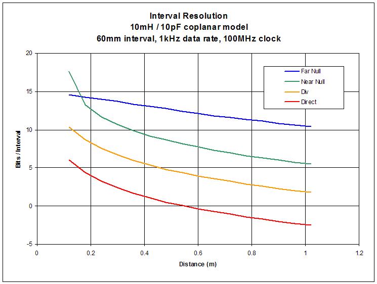
This is preliminary, but interesting:

It uses the coplanar hand capacitance model as input.  450mm long / 10mm diameter antenna, 10pF stray capacitance, 10mH inductor.

"Far Null" is heterodyning with a 1kHz beat at the maximum chart hand distance (fixed oscillator above the variable).

"Near Null" is heterodyning with a 1kHz beat at the minimum chart hand distance (fixed oscillator below the variable).

"Div" is dividing the variable oscillator down to ~1kHz (no heterodyning).

"Direct" is measuring the variable oscillator directly (no heterodyning).

All are followed by a low pass filter set to 1kHz.  All measure the period with a 100MHz clock.

Shown are bits of information per interval, and the hand distance interval here is 60mm.

Not sure how noise affects things, but "Direct" might fare better than it's fairly dismal showing above in the presence of noise.  The Open.Theremin (and I presume the Theremini?) employs "Far Null".  The Smirnov designs employ "Div".  (I'm also not sure where the method I've been using, DLL + LPF, fits in this picture.  A form of "Direct" I suppose, but I think there is a lot more information not accounted for / shown due to the fairly high resolution of the phase error accumulator and NCO.)

Grain of salt, I might be looking at this entirely wrong.

Posted: 2/1/2014 9:16:42 PM
FredM

From: Eastleigh, Hampshire, U.K. ................................... Fred Mundell. ................................... Electronics Engineer. (Primarily Analogue) .. CV Synths 1974-1980 .. Theremin developer 2007 to present .. soon to be Developing / Trading as WaveCrafter.com . ...................................

Joined: 12/7/2007

Hi Dewster,

That looks facinating, but im not sure I understand whats going on..

You say ""Far Null" is heterodyning with a 1kHz beat at the maximum chart hand distance (fixed oscillator above the variable)." - What I am confused about is the topology / reference oscillator frequency you used to get these plots.. Was the 10mH part of a "tankless" topology? (I assume this because I know your dislike for the other topology ;-)

The Open.Theremin would then be (if I remember correctly) conformant to this plot (I dont think it has a seperate tank and antenna resonator) but the theremini probably wouldnt (I suspect it has the standard EW topology)

The "near null" isnt a scheme I have seen used AFAIK.. This would, as I understand it, be operating in the "wrong side of null" zone, which would lose even the little "natural" linearity conferred by the distance-capacitance relationship..

The direct and Div modes should correspond closely (if not identically) to a plot of the antenna capacitance, I would think..

Fred.

Oh, just realized - bits / interval puzzles me as well .. What "interval" are we talking about? And are you actually saying that there are 10 bits of resolution (for example) "within" this interval? ..

oops - just seen "60mm interval" ;-) I was thinking musical intervals - no surprise I was confused! ;-)

You must be logged in to post a reply. Please log in or register for a new account.