Let's Design and Build a (mostly) Digital Theremin!

Posted: 2/1/2014 11:29:37 PM
dewster

From: Northern NJ, USA

Joined: 2/17/2012

"What I am confused about is the topology / reference oscillator frequency you used to get these plots.. Was the 10mH part of a "tankless" topology?"  - FredM

It could be tankless with 10pF stray.  Or it could be series, or parallel, with 10 mH tank inductor and 10pF tank capacitance and with no EQ L.  I believe they are all equivalent here.

"Oh, just realized - bits / interval puzzles me as well .. What "interval" are we talking about? And are you actually saying that there are 10 bits of resolution (for example) "within" this interval? .."

That seems to be the case (in the absence of noise).  I'll think/work on this some more and report back.  I'm anxious to try "Far Null" out in practice to see how it behaves.  (Can't believe it's been almost a year since I've done any directly related Theremin FPGA work.)

Eric

Posted: 2/1/2014 11:56:43 PM
FredM

From: Eastleigh, Hampshire, U.K. ................................... Fred Mundell. ................................... Electronics Engineer. (Primarily Analogue) .. CV Synths 1974-1980 .. Theremin developer 2007 to present .. soon to be Developing / Trading as WaveCrafter.com . ...................................

Joined: 12/7/2007

"I believe they are all equivalent here" - Dewster

Yes, I suppose they would be... So here I am wondering.. The Far-Field mode with 1kHz "bias" gives the best resolution - this is a function of the heterodyned output being sampled at 100kHz..

The thing which jumps at me from the L and C values you have selected, is the huge frequency change these will cause (compared to a design for outputting audio) - 10mH + 10pF = 503.29k,  10mH + 11pF = 479.87k .. A massive 23.42kHz / pF, with a normal theremin where the heterodyned signals (difference) is output as audio, one is looking for perhaps 4kHz/pf (non-linearized) max... The scheme you are proposing could easily occupy a bandwidth of 50kHz !

Such a wide frequency variation certainly wont suit the series LC linearizing topology. Not a problem if linearization is done in the processing..

But for the theremini, I would be surprised if they have deviated so greatly from the EW front-end... And as I see it, your high resolution is dependent on the large frequency variation, something the EW topology wouldnt easily allow..

Fred.

ps - did the sums on a calculator and they could be wrong.. But I think you are onto something.. This does look like an extremely promising way to increase resolution!

An analogy would perhaps be something like this.. Using an LC with fixed drive frequency to obtain a voltage output (like a volume circuit) one wouldnt use 455kHz into a 680uH with 180pF, and strap the antenna across this - resolution would be low - you'd use a ~10mH direct to the antenna... But, for a normal audio-outputting theremin, the 680uH + 180pF + antenna gives adequate sensitivity for the pitch side..

" (Can't believe it's been almost a year since I've done any directly related Theremin FPGA work.)"

You know, I know this sort of feeling well! - But look on the bright side - imagine you had finished your theremin a few months ago, and laid out the money for boards etc.. And were about to launch your product - Then the Mamm bombshell hit... This way, you have a chance to assess everything in the light of the theremini - The dynamics / market has changed, the prices one can charge has changed - It may well turn out that the delay will serve you.

Posted: 2/2/2014 3:15:38 PM
dewster

From: Northern NJ, USA

Joined: 2/17/2012

So I stuck the linearization sheet into the resolution spreadsheet and the results are quite interesting:

The above is "Far null" with 15mH tank inductor and 20pF "stray".  100MHz sampling frequency, 1kHz data rate.

By manipulating the tank inductance and stray capacitance I can get a fairly linear pitch response from the model (blue lines above).  This is measuring the period rather than the frequency.  I can get it to do the familiar "bathtub" sensitivity curve as well with some manipulation.  It seems to tolerate a lot of stray capacitance, which means passive shielding is perhaps a real option.

Spreadsheet is here: http://www.mediafire.com/view/vimtpm69k75p4kx/Sampling_Methods_2014-02-02.xls

Eric

[EDIT] The top chart title should be "Offset Beat Period vs. Hand Distance" or similar.

[EDIT2] Kudos again to the Open.Theremin project for suggesting both offset heterodyning and period rather than frequency measurement.

Posted: 2/6/2014 1:49:36 PM
dewster

From: Northern NJ, USA

Joined: 2/17/2012

"But this one has me puzzled - Whats the problem or difficulty with digital heterodyning? All you do is take one oscillator to the CK of a D latch, and the other oscillator to the D input of this same latch.. The output is a square wave at the difference frequency of the to input oscillators."   - FredM

Heterodyning with a latch might work for musical tone applications, but it seems too limiting for digital informational purposes.  Say you have two frequencies, F1 and F2.  F1=250kHz, F2=251kHz.  Feed F1 to the CK, F2 to D.  The Q output is |F1-F2|=1kHz, but the output edges can only change on the rising edge of the input clock (F1).  So the output periods are quantized to 1/250kHz=4us.  You can think of this as phase error as being bounded by +/-2us, or as phase noise. 

If we are measuring the 1ms period of the heterodyned output, we would only be able to resolve it to 4us.  1ms/4us=250 or ~8 bits.  We can't improve this via averaging without negatively impacting response time. 

If we having a 100MHz system clock for measuring, then we're throwing out 100MHz/250kHz=400 or over 8 bits of information.

===========

A better approach might be to use multiplication, like XOR, followed by low pass filtering.  This gives a non-quantized |F1-F2| output waveform, but unfortunately also gives F1+F2.  The issue here is F1+F2 must be way far away from |F1-F2| for simple filtering to give monotonic zero crossings (required for digital sampling).  One might also use a higher order filter to encourage monotonicity, but since |F1-F2| can have a lot of range, a fixed filter will give varying amplitude.  This BTW is the method the Open.Theremin uses, XOR followed by an analog 3rd order LPF.  The Open.Theremin seems to be a mother lode of practicality.

Posted: 2/6/2014 3:30:56 PM
FredM

From: Eastleigh, Hampshire, U.K. ................................... Fred Mundell. ................................... Electronics Engineer. (Primarily Analogue) .. CV Synths 1974-1980 .. Theremin developer 2007 to present .. soon to be Developing / Trading as WaveCrafter.com . ...................................

Joined: 12/7/2007

"Heterodyning with a latch might work for musical tone applications, but it seems too limiting for digital informational purposes.  " - Dewster

Yeah, your arguments are sound.. I have used this mostly for generating ramp waveforms using XOR and other logic.. I also used ~455kHz, but I think the waveshaping and the integration of this probably caused any switching error in the composite waveform to be lost.

But I think there might be a simple fix for the problem.. Use two D latches, one clocked by the variable, one by the reference - that way if you sum the two counts I think you get rid of the errors.. I hadnt done any calculations so never realised how significant the errors were, but had thought of double counting in this way (mainly because there was a spare D latch! ;-)

Fred.

(I may be wrong on the above - need to run some sims..)

Hmmm ... It does seem like the two latch method only reduces the error by 50% - Yeah.. The XOR is effectively analogue and completely unquantised.. Just wonder if one can take the XOR output into a pulse width discriminator so that one gets a "trigger" when the width is teeny (<100ns ?) and use this, rather than requiring a LPF and crossing detector.

Nope - the above doesnt work either.. still quantized..

Posted: 2/6/2014 10:37:07 PM
dewster

From: Northern NJ, USA

Joined: 2/17/2012

"The XOR is effectively analogue and completely unquantised.."  - FredM

True that.  Here's an Excel simulation:

This is two square wave output DFS (digital frequency synthesis) oscillator blocks XORed together with the result digitally low pass filtered.  Master clock is 100MHz, DFS accumulators are 20 bits wide, with the phase increments set to 300kHz and 330kHz.  The low pass filter is two first order sections cascaded, and they are identically set to an approximate cutoff of 15kHz.

The output of the first filter section is quite jagged and unusable from a zero crossing perspective.  The output of the second section appears to be smooth enough (the sim has zero crossing counters and I haven't seen the second misbehave with limited playing around).

Here's the file: http://www.mediafire.com/download/soir7vlwjh6a3jr/heterodyne_study_2014-02-05.xls

Posted: 2/7/2014 10:40:17 AM
livio

Joined: 2/2/2014

As you are trying to find out the impedance and capacity optimum values, for your digital theremin project. I have some advice about it, which I hope could be of interest. I would recommend you take a look at our CapSensorHQ schematics, here: www.theremino.com/en/technical/schematics#capsensor

Important points for maximum stability:

1) Use a low noise and high gain FET (basically the best choice is a BF862)

2) Use as impedance approximately 330uH and a total capacity, sufficient to obtain approximately between 2 and 3 Mhz frequency (over the medium wave and before the short waves). this band of frequencies is interference-free and using a high frequency allows a better resolution while counting for a short time (30 ms). To count for a short time is needed to have a fast response (30 Hz)

3) Use as L1 inductance, a TDK SMD, otherwise the temperature stability would be bad.

4) Use an oscillator configured with much capacity between gate and ground, so as to minimize the frequency temperature dependence, caused by the FET.

5) Do not try to linearize the oscillator in hardware, because this would worsen the other features

6) Linearize in software (or firmware if you want to make an instrument not connected to a PC)

For electronics advices I'm always available here or on Skype : livio_enrico, while for musical topics, please contact Massimo (ortica on this forum): www.theremino.com/en/contacts/about-us

Posted: 2/7/2014 4:58:02 PM
dewster

From: Northern NJ, USA

Joined: 2/17/2012

"2) Use as impedance approximately 330uH and a total capacity, sufficient to obtain approximately between 2 and 3 Mhz frequency (over the medium wave and before the short waves). this band of frequencies is interference-free and using a high frequency allows a better resolution while counting for a short time (30 ms). To count for a short time is needed to have a fast response (30 Hz)" - livio

It's been my experience that 30ms / 30Hz isn't fast enough response for a Theremin, not sure I'd go below maybe 4ms / 250Hz.  Too much delay gives sluggish seeming response, and in the extreme might lead to operator induced oscillations.

Humans start detecting audio event anomalies around 1ms or so.  This makes sense because the speed of sound is 340 m/s, or ~1 foot/ms, and we can echo locate to some degree.

"3) Use as L1 inductance, a TDK SMD, otherwise the temperature stability would be bad."

What's the part number?  The inductors are often the weakest link in any new Theremin design.

"5) Do not try to linearize the oscillator in hardware, because this would worsen the other features

6) Linearize in software (or firmware if you want to make an instrument not connected to a PC)"

I agree with that.

What do you do your Windows software apps in?  They look very nice!

Posted: 2/7/2014 6:13:57 PM
livio

Joined: 2/2/2014

Update frequency
-----------------------------------------------------------------------------------------------
Yes, naturally 30 mS is a "minimum" to get good results.
Normally we use 5 mS and an USB exhange rate of 500 Hz (2 mS) but we have tested (with blind tests)
that below around 20 mS no one can appreciate differences.

You are right that in audio 1 mS is audible but this is true regarding waveforms and samples, not on frequency changes.

To be sure we add some margin, and say that a 10 mS (about 100 Hz) is good.
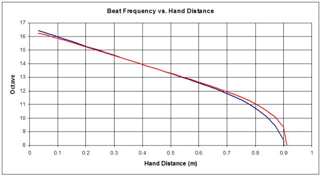
Resolution
-------------------------------------------------------------------------------------------------
How many oscillations of a 330 KHz are in 10 mS?  Only 3300.

But not all the 330 KHz can be changed with the hand, a reasonable change is about 10%, 33 KHz of variation. 

If we digitalize with a counter, we get a resolution of 33 KHz /100, that means 330 steps only, absolutely not enough to be precise. (10 Hz beats when playing a 3300 Hz note)

It is better to work with a resolution about then times higher, and this is the reason to use our 3 MHz frequency.

Maybe 600 or 800 KHz could be enough, but unfortunately the 550 KHz to 1600 KHz range is the "Medium Waves" band, and the first following range really free of interferences, is from 2 MHz to 3 MHz.

About the inductor
--------------------------------------------------------------------------------------------
We choosed a TDK SMD inductor after testing many inductor of any dimension, also DIY and also the very large inductors suggested from the Theremin literature. 

The TDK NLV32T-331J-PF (marked 331J on the body) are absolutely better than any other.

Farnell: 1669943
RS: 548-2895
Mouser: 810-NLV32T-331J 

About the software
--------------------------------------------------------------------------------------------
All our software is written with Visual Studio 2008 Express - free from Microsoft for any non commercial usage (we are an Open Source and No Profit organization) 

Posted: 2/7/2014 7:02:50 PM
dewster

From: Northern NJ, USA

Joined: 2/17/2012

"Normally we use 5 mS and an USB exhange rate of 500 Hz (2 mS) but we have tested (with blind tests)
that below around 20 mS no one can appreciate differences.

You are right that in audio 1 mS is audible but this is true regarding waveforms and samples, not on frequency changes."  - livio

Hmm.  I guess I disagree.  If you wave your fingertips very quickly side to side near the pitch antenna (making the whole hand flutter from the wrist) you can tell when the response time is too low by the shallowness of the pitch response.  Also, touching the antenna on a real analog Theremin will provide an instantaneous and abrupt pitch shift.

"How many oscillations of a 330 KHz are in 10 mS?  Only 3300."

This is what we are currently discussing.  If you heterodyne (analog or digital) and measure the period rather than the frequency, you can dramatically increase resolution.  Having a high speed clock with which to do that counting helps a lot, and this is where an FPGA really shines in comparison to a processor.

"Maybe 600 or 800 KHz could be enough, but unfortunately the 550 KHz to 1600 KHz range is the "Medium Waves" band, and the first following range really free of interferences, is from 2 MHz to 3 MHz."

Very interesting.  There hasn't been enough investigation in this area IMO, as most Theremin builders don't have the luxury of decoupling capacitance sensing from audio pitch generation.

But, as you know, there is more to sensitivity than simple operating point.  If the antenna is connected to a relatively high capacitance point the sensitivity will be lowered.

"The TDK NLV32T-331J-PF (marked 331J on the body) are absolutely better than any other."

Thanks!  No temperature data in the datasheet, unfortunately (par for the course).  I'm currently avoiding anything with ferrite for temperature stability reasons.

Over on the other thread you posted temperature stability simulations for your design.  Where did you get the inductor temperature dependence, or was this not part of the simulation?

You must be logged in to post a reply. Please log in or register for a new account.