


Let's Design and Build a (mostly) Digital Theremin!
Posted: 6/5/2016 2:00:16 PM

SPI MASTER
I coded up a simple SPI bus master in System Verilog and installed it in Hive (gave it register set support). One could just connect SPI devices to GPIO pins and have at it, but that would be kinda slow. Anyway, here is a simulation of it:
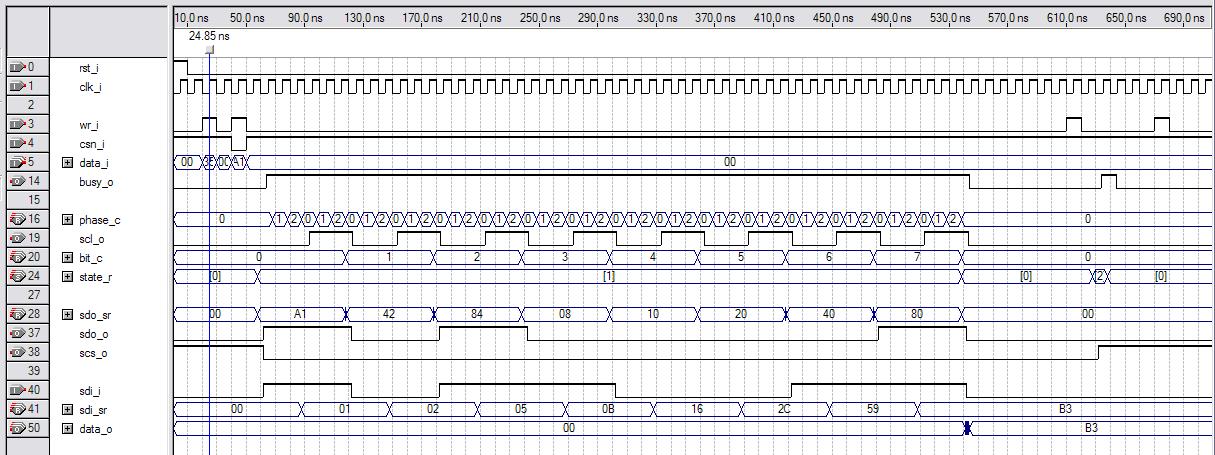
This is the simulator built-in to the Altera Quartus tool doing a functional rather than timing-based sim. At top are system reset and system clock (the clock toggling all the logic). Below it are register write (decoded from execution of the register write opcode and the specific register address) and input chip select (a bit in this register that it shares with the tx data byte). Note that the input chip select has to be low before a write will initiate a SPI bus cycle, and that the write data is provided at this point also (0xA1 here). While a cycle is going on a busy indicator is sent back to the processor (a read bit in the same register that it shares with the rx data byte).
Internally a phase counter counts the clocks in each bus clock (scl_o) high and low period, and this is configurable at build time to easily provide slower bus timing than the system clock (SPI memory devices are fast, but not as fast as the Hive system clock, which can be ~200MHz). The SPI bus clock acts like a counter bit which resolves full clock cycles, and next we have a bit clock counting the bit cycles below this, which lets the logic know when a byte is complete. A simple three state state machine tracks global state (idle, busy, SPI chip select deselect).
You can see that the serial data (sdo_o) is sent MSb first, and that the bits change when the SPI bus clock transitions low, and sampled on clock high transitions. This is true for both bus entities (master & slave). SPI bus chip select (scs_o) is active low from the beginning of the cycle until we disable it, and this allows us to send & receive multiple bytes via multiple writes to the Hive SPI register. Note that the SPI bus doesn't have a read / write indicator, reading and writing (and other operations) are defined by the first byte sent in a transaction (when the SPI chip select goes low). For reads and writes, a 24 bit address follows this byte, and write or dummy data (for a read) follow this. Above you can see the value 0xB3 being read from the bus (sdi_i) and sent back to the processor for reading (data_o).
I made the busy bit [31] in the read register, which allows for simple jump testing in software via the sign. The read and write data are double buffered, but I don't think I'll be taking advantage of this in software. Double buffering keeps the parallel data around between cycles making it easier to supply and catch with slower processes, and it also decouples timing to some degree which is mainly why I use it here. In actual use I plan to have the SW do an interlocked cha-cha loop: read data, then write data, then wait for the busy flag to go low, etc. Checking the busy flag also reads the data, so these steps can be combined. For this Flash memory device, the SPI bus clock works all the way down to DC, so we can wait as long as we like between bytes. Note that I implemented SPI mode 0 here, wherein the SPI bus clock is quiescent low.
This kind of basic simulation really has to be performed for all low level SV components (even those that are this trival) because there is often no easy way to figure out errors up at the top when many components are interconnected and things start getting complicated. I very much enjoy this kind of interactive simulation, which you used to be able to do with Quartus, I really wish they had retained the simulator in their tool (v9.1 sp2 was the last of the Mohicans).
Posted: 6/5/2016 5:06:23 PM
It seems I was beaten to the punch with the invention of Hive's pop bit, Mark Shannon described such a construct in his 2006 MSc Thesis:
https://www-users.cs.york.ac.uk/chrisb/main-pages/publications/ShannonThesis2006.pdf.1
Interesting read, but if you look at his "optimized" code there are still tons of stack manipulation operations, which are fundamentally inefficient.
Posted: 6/5/2016 5:23:45 PM
dew said: "You can see that the data is sent MSb first, "
Yeah, I really could not miss that. In my day of assembly cowboy coding I did a lot of stack pushing and popping as a quick and fast memory shortcut, the fewest operands but that could get out of sync if not careful.
A theremin is two RF Oscillators, a mixer and audio amplifier, nothing more. Which part are we looking at in your demonstration to simplify the approach, make the proximity more linear and the sound more pleasant?
You can call this a theremin, I am sure it is better than a cell-phone theremin app.
Did you know the outer edge of the butterfly wing is called Termen, very delicate.
Christopher
Posted: 6/5/2016 5:46:46 PM
"A theremin is two RF Oscillators, a mixer and audio amplifier, nothing more. Which part are we looking at in your demonstration to simplify the approach, make the proximity more linear and the sound more pleasant?" - Christopher
That the heterodyning of two oscillators can give an OK approximation of pitch linearity to our logarithmic ears is quite interesting. And that the act of mixing them can give an OK timbre is also nice.
But these fortuitous things can be chains that bind developers and keep them from going to the next level of linearity and timbre, where the tight coupling of features is counterproductive. I'm showing in (excruciating?) detail my attempts to pull it all apart, to divide and conquer.
Do a Google image search for "metal detector schematic". It's fascinating to see how far technology that was initially very similar to the Theremin has evolved over time. If Theremins were anywhere near as common than metal detectors I think we'd see a lot more in the way of technical movement in the field.
Posted: 6/7/2016 3:10:38 PM
Yesterday I got back to hardware by trying out various Hive programs on the FPGA demo board. Wrote a quickie that does UART loopback via software and found an RX ready read timing bug that I fixed by adding a flop (the internal register set timing is a little tricky if you are handling clear-on-read timing manually in logic, rather than via the pre-defined canned register set constructs). Translated the bouncing LED MIF code to HAL and that worked first try.
And I finally came up with an efficient way to convert ASCII Hex to numbers, I can't believe how many hours I've put into this trivial 16 line subroutine:
0x40 P0 -= 48 (s0<0) ? pc += 10 // bad s0 -= 10 (P0<0) ? pc += 11 // OK, 0-9 P0 -= 17 (s0<0) ? pc += 6 // bad s0 -= 6 (P0<0) ? pc += 6 // OK, A-F P0 -= 32 (s0<0) ? pc += 2 // bad s0 -= 6 (P0<0) ? pc += 2 // OK, a-f P0 := -1 // bad, return -1 pc := P7 P0 += 10 // good, offset A-F pc := P7
The trick is to divide good / bad value areas as negative / non-negative via subtraction, then jump or continue to decode further based on that. Most of the subtractions have to happen anyway, and the code will accept either upper or lower case A-F. Too bad whoever invented ASCII didn't make the 0-9, A-F codes match up with their hex values. They could have at least made 0-F contiguous, but no. Going from a hex value to ASCII is trivial (takes ~4 lines of HAL).
This morning I expanded the HAL parser / disassembler to optionally employ the "-=" syntax with immediate adds and jumps, which makes things like "P0 += -45" easier to read and write as "P0 -= 45".
Now I'm mulling over boot loader strategies. Something simple to take ASCII hex over UART and stick the values in memory, while all threads but one spin at a single address, then clear the threads to kick it all off. I've been at this point before with previous stack processors, but never with this level of simulator and assembly language support.
Posted: 6/9/2016 2:16:36 PM
Pump You Up
Thinking about the various ways to do code upload to a target processor. RS232 is becoming quaint for this kind of thing, but RS232 over USB is still alive, and USB is currently providing 5V for the demo board via a serial TTL / USB cable, so it's a natural.
If the baud rate is 115200 and there are 11 bits per byte (1 start, 8 data, 2 stop) then the byte rate is roughly 10kHz. If we employ only printable ASCII characters to express the byte value, we will be sending less than one byte of data for each serial byte sent. Hex could be used, which would give 50% efficiency tops. Since Hive main memory is likely to max out at 32kB for this project, it would take 2 * 32k / 10k = ~6 seconds to send this via ASCII hex, which isn't exactly light speed, but doesn't seem terribly onerous either.
Looking at the defacto standards like Intel Hex, I'm not sure what the exact goals are for them. Compact file size? Per line transmission correctness? Beats me. One can easily run a CRC32 routine over a region of code once it has been uploaded which would catch more errors than a checksum. And who cares how big files are these days?
I've made it a point to avoid states or "modes" with both the Hive core and Hive simulator, and this has worked out really, really well. The only real simulator mode is whether it is executing code or not, but even this is just looping using the single step command, so it's more of an extrapolation or automation of basic functionality. I suppose this is driving me towards the avoidance of an explicit upload "mode" for the processor boot code, though this will clearly negatively impact code upload efficiency.
The simulator has a "wm" command which takes an address, 32 bit data, and the "wm" command itself, and performs a write to memory. If the address is omitted (detected by counting command line tokens) then the highlight address is used as a default. Using something similar for code upload, the first write could give the starting address and first data, and subsequent writes would use the default incremented address.
If there are to be other commands in the command set then we need to make sure they aren't misinterpreted. Writing text parsers has given me a lot of insight into the low-level mechanics of the syntax of a language like C. Numbers always start with 0-9, and starting hex numbers with "0x" signals the multiplier for subsequent digits to be 16 rather than 10, and '0' is a benign starting point for the value itself. Keywords and variables never start 0-9, so token parsing is fairly simple.
So, if we use standard C hex notation, what would the efficiency be? Transmitting three full 32 bit hex values would entail something like:
 0xFFFF 0xFFFFFFFF wm
 0xFFFFFFFF wm
 0xFFFFFFFF wm
The spaces are transmitted bytes, as are the line breaks. Ignoring the address for long sequences of writes, it would seem to require 14 bytes per 4 bytes stored, giving a 32kB upload time of 6 * 14 / 4 = ~21 seconds. However, many lines could likely be compressed, particularly those which are NOPs or blank, or those which can be expressed by small values:
0 wm
This is where I am at the moment. I've taken another look at the CRC32 algorithm and made it a bit more efficient by using a rotate opcode rather than a shift, with a slightly modified polynomial (MSb = 0):
0x40 s1 := 0x6db88320 // <<CRC32 sub start>> - poly s2 := 31 // loop idx P0 >>r= 1 // <loop start> rotate right 1 (s0!<0) ? pc += 1 // check MSb P0 ^= s1 // xor w/ poly if MSb is set P2 -= 1 // dec loop idx (S2!<0) ? pc -= 5 // <loop end> P1 P2 // clean up pc := P7 // return
Been adding features to HAL, above you can see how negative left shifts can be expressed as positive right shifts.
The way the CRC32 subroutine would be used is:
1. Invert first 32 bits of data (or XOR with all ones, same thing).
2. Call subroutine.
3. XOR next 32 bits of data with the subroutine result.
4. Call subroutine.
Repeat 3 & 4 until done with all data. If the encoding CRC was appended to the tail end of the code, and if there were no errors, the result should be 0xDEBB20E3.
[EDIT] In summary, I plan to use a simple command line interpreter to upload code. The sim has a "zm" command which zeros out memory, which I can easily implement here as well to smash huge blank swaths of memory. The programming file will then be a series of commands that contain data, rather than just raw data. Mapping MIF or raw memory array contents to the programming file should be straightforward. Checking afterward via CRC32 and even flashing can be incorporated in the programming file as well.
Posted: 6/16/2016 10:33:00 PM
A week in from my last post and I've got a lot of the underlying functionality done for the bare bones command line / monitor / sub boot thing. With all the jumps and such, assembly can instantly turn into spaghetti code. The main trick to managing the complexity seems to be time-honored factoring into subroutines. So it's all divide and conquer, with basic subroutines for UART TX, RX, ASCII to BIN | DECIMAL | HEX, HEX to ASCII, white space detection, etc. A subroutine that tokenizes the input is finished. It passes the results to a token parser subroutine which is just a skeleton at this point. And a subroutine that interprets and transmits 32 bit HEX and packed ASCII is done. In a way it's fun, but I can see why no one codes in assembly unless they just can't help it, as it isn't a super efficient use of the programmer's time.
Been grappling with the best way to program in HAL. Assembly language is simple, but it's definitely learning yet another language. It feels somewhat like back when I was programming some of my earlier pure stack processors, as there are plenty of opportunities to dither and fret over efficiency and operation count, but the multiple indexed stacks in Hive provide much relief from this. With a cannonical stack machine you invariably waste a significant fraction of cycles just getting things lined up for the ALU, and the anxiety levels from looking for ways to trim one more instruction (usually at the expense of readability and therefore maintainability) are just too much for my poor brain. I've learned that tricky solutions are generally sub-optimal for a variety of reasons (e.g. trouble divorcing the beautiful trick when it stands in your way).
Anyway, I can see why soft labels and such are features of most assembly languages, as micro managing address in a text editor is fairly painful. Add enough automated features in assembly and before you know it you're edging into high level language territory. With the token parser I'm grappling with data interpretation, or typing at the lowest level. It's all quite fascinating from a historical perspective, with ontogeny recapitulating phylogeny and all that.
Posted: 6/22/2016 12:44:07 PM
Yet another week in and I've got address label support working in the HAL parser.
The low hanging fruit here are the thread clear and interrupt vector addresses, which I've decided to use the symbols CLT[0-7] and IRQ[0-7] for, respectively. So e.g. CLT[4] in HAL code gets replaced by the thread 4 clear vector address. This is simple pre-processing substitution of token patterns with hard wired address values obtained from constants in the package.
I've also got more generic LBL[] address labels working. The way they work is via explicit or implicit assignment. An example of an explicit assignment is:
LBL[3] := 0x45
on a line by itself, which obviously assigns the address 0x45 to label 3. Label 3 must be null prior to the assignment or this is an error.
An example of implicit assignment is:
LBL[4] <some code>
where a null LBL[4] is assigned the current running address. If label 4 isn't null then the label is replaced with the assigned label value.
A label showing up in place of a literal:
P4 := LBL[4]
also replaces the label with the assigned label value, and the use of an uninitialized (0, null) label here is an error.
Labels can also be used for constant non-zero data if desired.
Ideally, labels would have easy to use names like SIN or PI or whatever, but I thought I'd start here and see how cumbersome a simple indexed array construct is to use. Labels are nice because they keep you from having to micro manage addresses you don't really care about in an absolute sense. For example you might want to stick a bunch of subroutines somewhere with no spaces between them, but still have the option of easily adding or subtracting lines of code from them without changing every reference in the rest of the code to their calling addresses. Or you might want to have a handy flexible table at the beginning of your code which nails down the locations of various entities in memory space - things like thread start points.
===========
One thing that is difficult to deal with in programming languages is the chicken or egg situation where A and B need to reference each other directly, but they are necessarily defined sequentially. C gets around this with header files, but that seems like a kluge to me. Mandatory prototyping header files in VHDL were something I was really glad to leave behind with verilog and SV. No one likes to type any more than necessary, and the extra *.h files tend to clutter up directories.
===========
The cases for hardware support of main memory byte access that I've encountered are iterative algorithm initial value tables (to reduce the number of iterations) and data storage / buffering of ASCII and other byte data (B&W image pixel values perhaps). Whether these are worth hardware support is probably debatable. Anyway, to slightly facilitate the parsing of bytes stored in memory I changed the Hive 16 bit memory read to unsigned.
Posted: 6/22/2016 7:16:39 PM
HAL Parsing
Here is a quick look at how to parse programming text files:
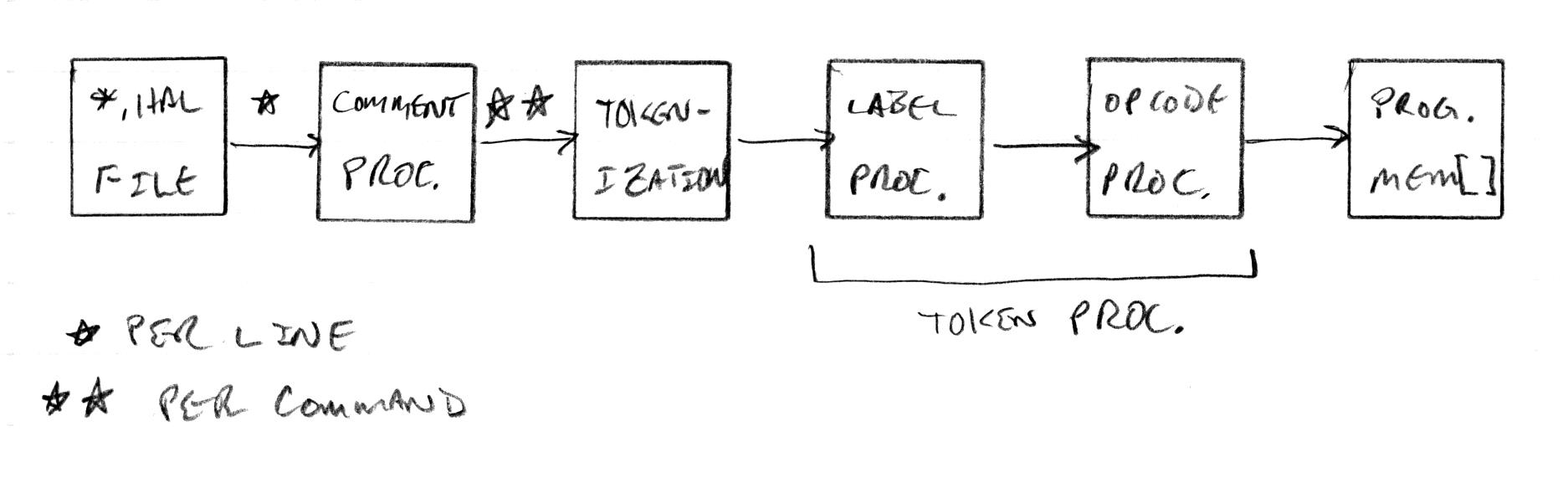
The input file is on the left, it is opened and one line at a time is fed to the comment processor.
The comment processor uses the rules of the language to separate comments from code content. If a block comment spans more than one line the comment processor waits until a code line is complete before handing the code line to the tokenizer. So the three states here are "in code", "in a block comment", and "in an end of line comment". It is safe here to add any amount of white space that makes the parsing easier - one could just replace the comment characters with spaces. Hal uses file end of line to indicate the end of a command, but C uses the semicolon.
The tokenizer takes the code line and slices it up. This is where your white space language rules get applied as extraneous white space is removed and meaningful white space is interpreted / added as token divisions. Any "special" symbols are given separate tokens. Otherwise contiguous alpha is kept contiguous (including the underscore character), as is contiguous numeric. The main job of the tokenizer is to make things uniform for easy downstream processing.
The token line then get handed off for token processing. First labels are assigned / replaced with actual address values. Then they are examined for pattern matching to commands. Any token line not matching a command is an error.
The output of the token processing is interpreted as machine code and stored in the memory array. The contents of this array can executed in the simulator, and can also be read out as *.mif files for hardware synthesis (BRAM initial contents = boot code).
============
I just made a cheesy command line linting tool for *.hal and *.mif files which works by enabling the verbose option in their respective parsers, which sends warnings and errors to cout. Pretty neat! It's interesting how, once you have a critical mass of code, new complex things can be done with very little effort.
You must be logged in to post a reply. Please log in or register for a new account.