Let's Design and Build a (mostly) Digital Theremin!

Posted: 9/16/2016 9:13:30 PM
dewster

From: Northern NJ, USA

Joined: 2/17/2012

LC AFE Board

Been kinda agonizing over this for too long, finally settled on values, vector board size, IC locations, etc.  Anyway, really old news for anyone following this thread, but the most critical construct by far for the project:

Still using the 74LVU04N hex inverter, and the Littelfuse SP721 for ESD protection.  I decided to use 100 ohm resistors pretty much everywhere as the RC delay is minimal, and this protects things between the separate power supplied circuits, as well as the CMOS ESD diodes, and gives nice signal integrity over the relatively long connecting wires.

And here is the physical view.  The FPGA board is at top, the power distribution / FLASH / SPDIF TX board is in the middle, and the LC AFE board is at the bottom.  It's connected to a 0.3mH air core on the left, and the test "antenna" is a 10pF cap.  On the LC AFE board the 3.3V LP295 regulator is at the upper left, the NPN / PNP driver just below it (socketed), the SP721 in the center of the board, and the hex inverter to the right.  I've got things arranged so that a second LC can be hooked up (for use as the two axis volume side).  With the dummy antenna the board draws ~30mA when unlocked, and ~15mA when manually adjusted for quadrature phase.  The signals look really nice!

After much experimentation, it's pretty clear that the phase reference also needs to pass through this board (the lower output in the schematic), as the various delays are just too long to ignore at ~2.5MHz.  This should help with temperature drift issues too.

Posted: 9/16/2016 10:55:38 PM
oldtemecula

From: 60 Miles North of San Diego, CA

Joined: 10/1/2014

Oh thank goodness you took focus off my hocus pocus.

We all have our favorite LC oscillator. smile

Littelfuse SP721 for ESD protection

At 3 pf loading I think you are going to be disappointed, I have thought about this over the years. For me it makes no sense.

My volume control insert wire approach is something to think about, I may do it for the pitch antenna but more for using the thinner wire and close proximity linearity. In any situation do not think it has to be high voltage insulation not being directly attached to the antenna.The static discharge would be dampened as it hits the metal surface and spreads out which then bleeds off to the atmosphere. The same principles could apply to a metal plate.

Let's see now, what will I work on next, free energy.....hummm   Einstein..  you talk'en ta me?

Christopher


Posted: 9/17/2016 1:38:49 PM
dewster

From: Northern NJ, USA

Joined: 2/17/2012

"At 3 pf loading I think you are going to be disappointed, I have thought about this over the years. For me it makes no sense."  - Christopher

Since the points being protected are fairly capacitive insensitive (tank NPN/PNP drive side; 100pF tank sense side) I think it all really depends on how stable that 3pF is (with temperature, etc.) and I haven't measured this.  The device is socketed so I can remove it if it's a problem. 

I agree that insulating the antennas largely obviates the need for ESD protection - my plates are inside plastic boxes and I don't intend to let them out. ;-)

Posted: 9/17/2016 5:08:50 PM
dewster

From: Northern NJ, USA

Joined: 2/17/2012

LC AFE Response

Hooked the AFE board up to the FPGA with my Hive processor in there and ran a script that varied the output period and measured the resulting phase error, then grabbed the data and pasted it into Excel for analysis:

This is over a frequency of 2.31 MHz to 2.25 MHz, and is using a 10pF capacitor as the "antenna" for testing.  If you do a bit of difference math in the spreadsheet you'll see that the slope around zero phase error is approximately 200.  This seems in the ballpark, though perhaps somewhat on the high side.  The gain of the phase detector is 4, so we're left with an LC phase gain of 50, which I determined via some math a while back to be equal to Q/pi.  So Q = 50 * pi = 157.  Actual Q with a real antenna will almost certainly be ~1/3 this due (presumably) to RF radiation.

From this, for phase lock, the accumulated phase error will need to be attenuated by more than 200 for loop stability.  Actually, since the accumulation will be happening at 48kHz, and the bandwidth of the phase error low pass filter is 1kHz, the required attenuation may be on the order of 200 * 50 = 10,000.

Posted: 9/18/2016 6:42:42 PM
dewster

From: Northern NJ, USA

Joined: 2/17/2012

Today I worked on the phase detector a bit.  It now uses an internal reference to dump the integrated error, rather than the external reference, thus sidestepping any glitching issues.  I'm pretty sure it doesn't matter much when the dump happens (as long as it is relatively consistent) because small error in any given period will be made up for in subsequent periods, and it's all low-pass filtered.  My main concern is in keeping low frequency aliasing from creeping in somehow and causing sticky points in the response.  While I was in there I removed the phase offset option because it likely won't be needed, and fixed the dump reset value to be an accumulate rather than a constant.  With all the hardware and software stuff going on there are zillions of opportunities for bugs, so I think my red alert paranoia level is justified.  Surprises are like news, none is good.

OT: Read this really interesting article on passive solar heating, a quote from it resonates with how I feel about my own research efforts:

"My attitude was that I would take as long as needed to get the job done – and that it would cost whatever it cost."

Posted: 9/21/2016 1:04:59 AM
dewster

From: Northern NJ, USA

Joined: 2/17/2012

HW / SW Phase Lock

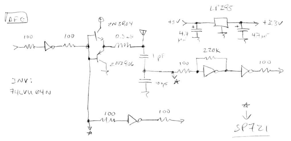
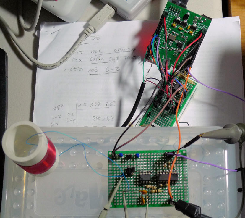
Got hardware phase lock yesterday via software in the loop - a first for me anyway.  The processor's thread 7 external interrupt lead is connected to the internally generated SPDIF 48kHz frame signal, so on every interrupt it reads the phase error (which is 4th order filtered in the hardware to -3dB @ ~1kHz low pass), accumulates it, attenuates it, and writes the resulting value to the numerically controlled periodic delay, which drives the LC tank.  The numbers are stored in Hive memory which I can manipulate via the Hive command line interface, so I've been playing around with it quite a bit.  At the moment the setup still looks like the photo a few posts above, with a 10pF dummy antenna.

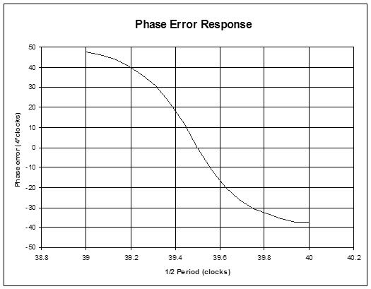
I'm seeing nice quadrature even if I grab the coil with my fingers and thus drastically lower the Q.  It won't start up without having the initial values somewhat in the ballpark, but I haven't seen it lose lock after that.  I have a script that walks through a series of attenuation factors which sets the loop cutoff higher and higher with each mouse click on the script dialog box button and it's very interesting to see the interaction of the Q based gain with loop stability (see the graph 2 posts up).  With gains that are on the border of stability, the instability is only AROUND the lock point, but as the phase error bobbles away from the lock point, stability clearly returns and tries to restore quadrature lock, but this causes the Q to increase and therefore the loop gain to go back up, which decreases stability, etc. so it acts like one of those pendulum gravity vs. repelling magnet executive toys.

I've also experimented with 4th order phase error low pass filtering via software.  It's pretty trivial to do, but it doesn't seem to improve things much, other than a general lowering of the feedback bandwidth - a gain thing more than anything else.  With this filter set to -3dB @ ~500Hz, the edge of loop stability is with an accumulator gain of 2^-12, which is quite a bit more loop gain than I was thinking was likely to work in a stable manner (but I haven't worked the math yet).

Also just experimented a bit with a software high Q comb filter to kill 60Hz, but it seems to make things somewhat noisier and less stable.  Maybe putting it inside the feedback loop is a mistake?  I've had high hopes for that filter, but I haven't messed with it enough to know if it will be useful or not, or even if I've implemented it correctly in software.

Anyway, almost no matter what I do I'm seeing ~200ns of jitter out at 50ms trigger delay, which is ~4ppm or so and somewhat more than I would like.  I'm sure using a real antenna this will be much worse, need to hook one up and see what range of stable numbers it can give.  This jitter could be coming literally from anywhere: environmental pickup, the fan on my PC, thermal noise in the logic inverter, dither noise in the NCPD, timing slop due to different clock domains and interrupts, etc.  I'll try to track it down, but everything is so exquisitely sensitive that may be impossible.

Posted: 9/23/2016 9:04:35 PM
dewster

From: Northern NJ, USA

Joined: 2/17/2012

Tried a bunch of stuff over the last few days, up to but not including "the big dirty" which would be to phase lock with a single clock, and all in hardware.  Didn't sleep well last night due to visions of phase detectors dancing in my head. Tried a new one out this morning but it didn't really change the behavior.  I'm coming to the conclusion that there is no simple perfect phase detector (wideband & noise rejecting) but there likely exists a "blend" that could do it all in this scenario.  Not that it really needs to because software is tightly within the feedback loop, but it's fun to think about.

The jitter seems fine really.  I've got it hooked up to a 268uH coil and a small piece of a license plate serving as an antenna, positioned less than 2 feet from my monitor and a fluorescent desk lamp.  The signal looks stable and clean, and it clearly reacts to my body over 1M away with 10ms scope delay (~100Hz bandwidth).  I should probably just keep going forward and deal with obvious troublemakers nearer to the end.

Posted: 9/24/2016 12:09:16 AM
oldtemecula

From: 60 Miles North of San Diego, CA

Joined: 10/1/2014

Dewster said:  "it clearly reacts to my body over 1M away with 10ms scope delay (~100Hz bandwidth)."

I can understand what you mention here but all the other digital stuff in your design is way over my head. I have done cowboy coding and assembly since the intro of the 8080 processor 35 years ago and still code when necessary today.

Not to be mean but what is the advantage or outcome of going from analog to digital then back to analog, this approach screams with latency which seems to consume most of your focus?

As a simple demonstrated example my ideal PWM volume has control over linearity by compensating the pulse width on the outer edge of the volume field and applying a greater width ratio there. No latency is introduced.

My Harmonic Exciter board as an accessory outputs a 5v square wave for frequency to voltage conversion but not recommended where latency would be an issue.

I like this tune below which demonstrates my ideal analog volume control without any latency or distortion.

40cm Dynamic Volume Control Window

Come back over to the light, the dark side does not need you, I do. I will be waiting with open arms. laughing

Christopher

Posted: 9/24/2016 3:05:59 PM
dewster

From: Northern NJ, USA

Joined: 2/17/2012

"Not to be mean but what is the advantage or outcome of going from analog to digital then back to analog, this approach screams with latency which seems to consume most of your focus?"  - Christopher

I should have been clearer in my description of the setup: the 10ms scope delay is trigger delay, not inherent latency of the circuit.  It shows me intuitively and roughly how good the data will be when band limited to 100Hz (1/10ms).  I'm not certain yet what the final playing bandwidth will be, it certainly needs to be substantially below 48kHz for stability of the feedback loop.  I'm pretty sure even 100Hz bandwidth would be OK for playing.  Where one might be able to perceive 100Hz playing bandwidth is with touching the antenna, where the phase error accumulator takes a while to wind up and down due mainly to the non-linear phase gain (Q) of the LC tank.  I'm thinking this might be somewhat ameliorated with a non-linear function applied to the phase error in software but it doesn't concern me all that much as it is now.  Even analog oscillators can poop out or act crazy when the antenna is touched (though I have seen players employ antenna touching used as a musical effect).

If it comes down to it I could also do the feedback purely in digital logic, where higher bandwidths would be much easier to do.  The ideal approach might be to accommodate any interference (i.e. high bandwidth) and filter it out downstream (i.e. outside the feedback loop).  I believe it mainly comes down to the dynamic range of the phase detector.

[EDIT] I can actually kind of do this with the current HW / SW loop, the loop feedback can be made higher bandwidth than the downstream feed.

"...what is the advantage or outcome of going from analog to digital then back to analog...?"

Analog designers don't necessarily think in these terms, but analog oscillators also have feedback gain and phase issues; with my approach I can deal with these independently and very flexibly, so it's divide and conquer.  The digital approach also simplifies the analog portion of the LC oscillator.  And musical synthesis should also be easier with DSP than with analog and a billion pots / patch cords, so digitizing the data as early in the processing chain as possible makes a lot of sense.

Posted: 9/25/2016 8:33:52 PM
dewster

From: Northern NJ, USA

Joined: 2/17/2012

Built a special pitch-side LC driver board today, very similar to the volume side board but a slightly different layout because of the single axis.  Spent hours yesterday trying to understand an apparent sign inversion in the loop feedback, only to notice there are three inverters in the LC side and only two in the feedback side on the volume board - doh!  When it comes to feedback sign, I find my first mental take is almost always wrong, so I was banging my head trying to get it to see a light that wasn't there!  The pitch board has three inverters in both paths to maximize thermal stability.

Environmental noise from the real antenna plate seems to perhaps help the stability of the lock, which is interesting.  It could be that natural dither is going on, breaking up modes.  I've got a different software low pass filter in there now but I'm not seeing a lot of up side having it in the loop, so it may get stripped out (or more likely moved outside the loop downstream).

That's the final big piece of the prototype circuitry done, so it's time to stick it all in the boxes and wire it up, and get cracking on the real software.

[EDIT] Speaking of software, I've been using a nifty feature in Quartus for the past couple of weeks that updates the FPGA memory initialization files without having to do a complete FPGA rebuild of the logic, which really speeds up software turnaround time.  I can edit the code in a text file, pull it into the Hive simulator and save it, copy the resulting MIF files to the FPGA build directory, do the update in Quartus, re-run the assembler, convert the programming files to target the demo board, and pump the FPGA in just minutes.  It might sound involved, but it's pretty quick and painless after you've done it a few times.

I really hope Intel won't screw with Altera's stuff too much now that they've been acquired and all.

You must be logged in to post a reply. Please log in or register for a new account.