Let's Design and Build a (mostly) Digital Theremin!

Posted: 11/30/2017 1:22:25 AM
dewster

From: Northern NJ, USA

Joined: 2/17/2012

Mystery solved.  Worked backwards through the pitch display and NCO code and was able to figure out the magic number offset to the display.  The exact value is 0x5C289612 because of the vagaries of note frequency mapping and the +298.4 ppm of the FPGA PCM PLL.

Still researching anti-aliasing, it seems to be a tough nut.  Even pre-computed waveform tables aren't a perfect solution, as harmonic content limit doesn't scale with oscillator frequency.  So designers turn to oversampling at the generator, or correcting harmonic causing waveform features manually (BLEP, polyBLEP, etc.).  To tame guitar distortion harmonics they use upsampling with an interpolation filter, distort, then downsampling with a decimation filter.  Yeesh.  I'm starting to lose hope that there is a generic solution one can feed anything to and kill aliasing.  Anyone got any ideas?

Polyphase filtering goes hand in hand with this sort of thing, which can dramatically cut FIR filter tap count, but I'm wondering if IIR might still be more efficient in SW (IIR gives phase distortion, which is generally inaudible).  Half-band filters look interesting, but I see them criticized for poor anti-aliasing performance at certain points in the signal chain (where they are apparently used in a lot of HW).

Posted: 11/30/2017 3:35:36 PM
dewster

From: Northern NJ, USA

Joined: 2/17/2012

Added variable power (in terms of multiplications) to the non-linear PWM transition tuner function to the menus, as well as a control to make the note display inverse (all LEDs lit except for the LED corresponding to the note).  Played with it a little but 4th power positive display still seems about the best.  The non-linear function helps the negative display too, though it's harder to tell which side of the note you're on.

Also am playing around with aliasing in Audition.  With a sample rate of 48kHz, generating a square wave sweep from 1kHz to 10kHz obviously aliases all over the place.  The thing is though, no amount of filtering gets rid of it, even really steep, really high order filtering, which is a complete surprise to me. Clearly one can mechanically round off sharp edges and dramatically lower the aliasing, or even better add Gibbs phenomenon, so why can't an in-band filter do this too?  Increasing the sample rate (Audition will do up to 192kHz) and then filtering helps a lot, but that's expensive when it comes to synthesis because one has to run the processes that much more often.  So I'm looking into upsampling, filtering, and then downsampling.  A CIC might actually work here too.

Posted: 12/2/2017 7:11:39 PM
dewster

From: Northern NJ, USA

Joined: 2/17/2012

Poor Man's Pitch Correction (Chromatic Quantization)

Now that I thoroughly understand the linear to exponential business on the pitch side (really have to do this stuff in an interactive spreadsheet) it hit me yesterday that I could use basically the same non-linear process I'm using to improve the readability of the LED tuner to quantize the pitch itself (ala the Theremini).

To do so we need to temporarily offset the tuner side NCO input value with a constant so that it lines up with the binary 5.27 format to isolate / extract the sub-note info and non-linearly process it.  Working backwards from C0 NCO output through EXP2 to the linear tuner side, we shift the value left 5 places (% 2^32) to find the octave fraction, then multiply by 12 (% 2^32) to find the sub-note fraction.  We then undo this by dividing by 12 (umult by 2^32 / 12) and shifting right 5 places, giving the constant value 8524950, or 0x821496.

To use it we subtract the constant from the NCO input value, and then separate out the octave, note, and sub-note values using the same shifts and multiplications we used to find the offset constant.  At this point we can non-liearly process the sub-note value, then recombine the octave, note, and non-linear subnote values, and finally add the constant back.

For the non-linear sub-note quantization function itself, I've picked a simple power here (described in a previous post).  The input slope is folded down (logical NOT) when the input exceeds 1/2, which gives a triangle.  We multiply this by 2 to get an output range of [0:1), multiply it by itself a number of times (the power here sets the quantization strength), divide the result by 2, and the output is flipped (logical NOT) if the input exceeds 1/2.  XOR may be employed to do the logical NOT, and shifts for the multiplication and division.  Decimal powers could also be implemented, though integer powers seem to give sufficient control over the process, and are much less expensive in terms of processor cycles.

So I've implemented this on the prototype and it works pretty much as expected.  Squaring gives quite mild quantization, 4th power is getting stronger, 8th and above is pretty strong, but even going way above this there isn't any hard "stepping" sound.  Not sure if I'll use it much, particularly as it kind of kills on-note vibrato (and accentuates off-note vibrato!) but it was an interesting thing to try out.  It's a first stab at actual pitch correction, which I believe uses more of a quantized PLL approach to things.

=============

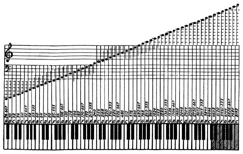
It's kind of a shame they didn't use 1Hz as the frequency basis of our note system, because it's already pretty close to just a 4 octave offset (16Hz) from C0 (~16.3516Hz).  C0 is only ~2.2% or ~37 cents above 16Hz.  (If we could go back in time and change things I'd pick note numbering rather than lettering, with C=0, and with chromatic rather than C major scale based intervals.)

Posted: 12/3/2017 9:08:27 AM
gerd

Joined: 11/25/2017

... wouldn't some kind of look-up-table with linear interpolation be faster and much more simple?

Posted: 12/3/2017 2:59:09 PM
dewster

From: Northern NJ, USA

Joined: 2/17/2012

"... wouldn't some kind of look-up-table with linear interpolation be faster and much more simple?"  - gerd

The note quantizer subroutine is only 28 lines of assembly with a minor loop, and the designer has to understand these things intimately anyway, so I'd say no.

I'm not sure if the quantizer is going to remain in the prototype as it has limited uses.  I'd much rather have real pitch correction.

Posted: 12/3/2017 4:13:28 PM
dewster

From: Northern NJ, USA

Joined: 2/17/2012

Pitch Field Linearity Solved!

Something I tried just now: pointing my open hand perpendicular to the face of the pitch antenna plate, putting the tip of my longest finger actually on the center of the (insulated) antenna, then closing my hand, I'm getting essentially the same open/closed hand linearity all through the playing field (0 to ~0.6 meters).  So linearity with this scheme (negative fractional power of the frequency difference, fed to an exponential oscillator) doesn't seem to significantly poop out right at the antenna (where my sims have no data but seem to suggest pooping out).  

I'm quite stoked by this!  It seems that, for all practical purposes, Theremin pitch field linearity has been solved all the way to the antenna.

It's pretty easy to dial in the parameters too.  Power-up calibration:

1. Adjust far-field null (P0) to get a response with no hand near antenna (much like an analog Theremin setup here).

2. Then check near-field open/closed hand response, adjusting the multiplier (P2) if necessary (it usually isn't).

3. Then check far-field open/closed hand response, adjusting far-field null (P0) until it is the same as the near-field response.

That's it!  The linearity parameter (P1) seems to be fairly constant and not in need of touch-up.  After calibration the multiplier (P2) and offset (P3) can be used to alter the pitch sensitivity and offset without affecting linearity.  But overall it's pretty much like setting up an analog Theremin. And no squealing when the (insulated) pitch antenna gets touched (squealing is a non-linear pitch field effect).

Posted: 12/4/2017 7:01:52 PM
dewster

From: Northern NJ, USA

Joined: 2/17/2012

Encodering Uppage

I'm coming to the conclusion that 4 encoders aren't really sufficient, and 4 values on the LCD (1 menu value and 3 parameter values) aren't either.  There are too many menus to page through even with the minimum functionality I've implemented thus far.  So today I'm going to wire up a 6 encoder board and work on the menu system.  I'm thinking 2 knobs to control menu and sub-menu, giving a line to each of these on the LCD, then 4 knobs for 4 parameters, with 1/2 a LCD line per parameter.  The parameters themselves can probably be displayed as small signed base-10 offsets or similar, 8 digit unsigned HEX numbers are likely too confusing / not all that informative to the average person (though they're great for development).

I put in two lines of assembly that copy the pitch number to P0 at power-up, which auto-nulls the pitch side.  The oscillators fire up immediately, and this copy is performed after the LCD reset timeout and initialization.  It works quite well, and I'll likely be adding this function to one of the encoder pushbuttons in the near future.

Posted: 12/6/2017 11:38:18 PM
dewster

From: Northern NJ, USA

Joined: 2/17/2012

Volume Side Thoughts

I got the new encoder board wired up and installed yesterday.  Now I'm thinking about how the various parameters are represented in the code and on the LCD screen.  The trick is to give the adjustments the right amount of "gain" per detent (though there is a square term or velocity applied for faster spins), to limit the adjustments to useful ranges, and to display them in a meaningful way (I'm not a fan of 0-10 or 0-100 type normalization, particularly when the underlying process is strongly binary).  Internally, the trick in the code is to do this in a systematic fashion so that adding / removing parameters is straightforward.  Having all the parameters in one spot in memory should make it easier to back them up to EEPROM or similar, and to recall subsets of them as "patches".  My current approach is to have the gain baked into the target code, and have the actual parameter (or offset thereof) value, hi/lo limits, and text label in a structure or table.

I really need to spend more time on the volume side of things, because at this point it's more or less a copy of the pitch side processing, and one size doesn't really fit all here.  For one thing, I don't think precision linearization is necessary for the volume control, we can just go with the stock linearity (power = -1, or take the reciprocal of the frequency difference) and no one will ever notice (stock linearity here is better than analog Theremin response).  The scaling and offset controls need to be better adapted to the smaller playing field, and I'd like to get them to the point where swapping the near/far sense doesn't require much fiddling.  I'm also going to try intentional non-linearity, as well as high-pass feed-through to see if that can give a sharper attack envelope.  Finally, I'd also like to try a delta arrangement with a larger field, where more movement of the left hand causes larger volume, rather like bowing a violin.  Perhaps this could be part of the high-pass feed-through arrangement.

Today I made the pitch side offset do octaves instead of notes, so it's a bank switch like on the EWPro.  Lots of ominous swells, wolf-whistles, finger-mouth popping, and bird chirp sounds were to be had!

Posted: 12/8/2017 1:28:46 AM
dewster

From: Northern NJ, USA

Joined: 2/17/2012

Yet More Encoderage

Yarg.  Going from 4 to 6 encoders strikes me as still not enough.  I can fit 8 reasonably sized parameters (4 digits and sign) and their labels (4 chars) on the LCD screen (2 per line * 4 lines) so why settle for 4 (2 per line * 2 lines, + menu + sub menu) with 6 encoders?  And why take up entire lines for the menu & sub menu?  Sub menus are kind of a pain to manage (do you remember where you were in each sub menu, or do you reset it when the main menu selection changes?) so if you have 7 parameter you can probably get by with a single menu depth.  Nothing precludes implementing sub menus later should that be necessary.

I removed and rotated the new 2 x 3 encoder board 90 degrees, and added a smaller board below it with the last 2 encoders in my parts box.  So there are now 2 columns of 4 encoders each (and the prototype front panel is starting to look like Swiss cheese!).  Soldered a header on backwards, and had to move a bunch of pin assignments in the FPGA, but it's all wired up and good to go now.  The moral here is don't solder or drill until you've mulled it over for a day or two, something my natural procrastination usually does for me (but unfortunately not this time).  Need to look into using the FPGA programmable pullups rather than raiding my resistor assortment for 10ks, and I should ground the encoder bodies to protect the FPGA inputs against ESD.

It hit me that I should not be using the null point on the volume side as an actual hard stop in the response.  The volume side should auto-null at power-up (like the pitch side does) and the downstream processing use some window of the values produced.  This will give the best linearity as well.  In most situations I don't think the volume side null would need any touch-up, as it is normally played near-field.  The volume side is turning out to have more nuance than expected.

Posted: 12/9/2017 7:12:26 AM
ILYA

From: Theremin Motherland

Joined: 11/13/2005

"  C0 is only ~2.2% or ~37 cents above 16Hz.  (If we could go back in time and change things ..." -- dewster

it may be interesting that in the new soviet republic, in 1930s, the C0 was exactly 16 Hz.

Source: S.N.Bronshtein - "Termenvox and Electrola".

You must be logged in to post a reply. Please log in or register for a new account.