Let's Design and Build a (mostly) Digital Theremin!

Posted: 4/13/2018 4:40:20 PM
DOMINIK

From: germany, kiel

Joined: 5/10/2007

Dominik, I'm studying your excellent video closely (what camera do you use?) but can't quite tell certain things from it due to the fast timing.  If you would be so gracious as to relieve my confusion:
1. It seems there is a diode or similar which favors the attack?
2. It seems there is a fixed RC decay time, could you perhaps tell me what that time (R*C) is?  
3. it seems that racing your hand towards the antenna can make the decay shorter?
Even though you don't use an explicit knee, I'm wondering if you are somehow (perhaps without realizing it) employing the non-linearity near the antenna?  If I jack the velocity up on the prototype I can get it to "trigger" anywhere, but that also makes the volume field pretty twitchy.Thanks!

I am happily using a Sony RX100 M3.

1. There is no diode. The 'bednarz-schaltung' (a friend called it so humorously) consists of an opamp, an electrolytic, six resistors and a potentiometer.
2./3. I have had to look it up again with a scope: decay behaves just like attack – velocity dependent. But the further away from the loop, the less velocity has an effect.

There are no fixed attack or decay events like in e.g. ADSR or AR or whatever envelope generators.
The non-linear positive or negative or zero acceleration of loudness is momentarily determined by the hands speed. Here i was writing:
- let A be the control voltage corresponding to the volume hands position.
- let B follow that voltage, but delayed. Like B'new=B'old+(A-B'old)/2
- A/B'new gives a multiplier to somehow generate the velocity voltage

I guess that was confusing.
Imagine you hold one end of a soft tension spring (let it be 20cm) in your hand. On the other end a somehow suited weight is being attached. If you slowly raise your arm, the distance between the hand and the weight won't differ. But a fast move up will stretch the spring in our example rapidly up to 60cm. While the weight after that move follows and settles smoothly in its normal position (in fact it would jump around wildly, but let our spring be a magic one). The lenght of the spring is the multiplier for the positive acceleration. Of course this example works for positive acceleration only.
I guess that was even more confusing.

Posted: 4/13/2018 10:27:27 PM
dewster

From: Northern NJ, USA

Joined: 2/17/2012

"I am happily using a Sony RX100 M3."  - Dominik

Thanks!  How are you handling audio and editing?

"1. There is no diode. The 'bednarz-schaltung' (a friend called it so humorously) consists of an opamp, an electrolytic, six resistors and a potentiometer.
2./3. I have had to look it up again with a scope: decay behaves just like attack – velocity dependent. But the further away from the loop, the less velocity has an effect.

There are no fixed attack or decay events like in e.g. ADSR or AR or whatever envelope generators.
The non-linear positive or negative or zero acceleration of loudness is momentarily determined by the hands speed."

Ah, much thanks for that info too!  It seems clear now - though I believe there is an RC time constant associated with the electrolytic and whatever resistance it "sees" - no? 

I think the problem I'm having replicating the behavior of your Theremin is that I'm using velocity, which is the differential of position, or a simple difference of the current position with the previous position.  I believe you are high pass filtering the position, which is the difference of the current position with the integrated past position.  That, and I'm rectifying the velocity and you aren't.

So there's a new test load in the prototype that uses unrectified high pass filtering, and I'm going to try it out for a few days.  Again, thank you for divulging your secrets!  You're a really good Theremin player too!

Posted: 4/14/2018 7:54:34 AM
DOMINIK

From: germany, kiel

Joined: 5/10/2007

Thanks for compliments. Of course there is always some room for improvement.

There might be RC time constants for attack and decay maxima (i cannot calculate those – trial and error will serve the purpose), but the RC time is floating inbetween..

High pass filtering the position.. Integrated past position.. Unrectified high pass filtering: i don't get it. 
Could you explain it for blondes, please?

Unfortunately the Sony RX100 M3 has no audio or mic in (unlike the M2). And with the integrated (hey: integrated again) mic being to far away from the amp recordings are so-so. Thus i use a JamMan looper as recorder. Premiere then brings it all together.

Can users (easily) build their own sounds with your theremin? A broad field.

Posted: 4/14/2018 8:35:17 PM
dewster

From: Northern NJ, USA

Joined: 2/17/2012

"High pass filtering the position.. Integrated past position.. Unrectified high pass filtering: i don't get it.  Could you explain it for blondes, please?"  - Dominik

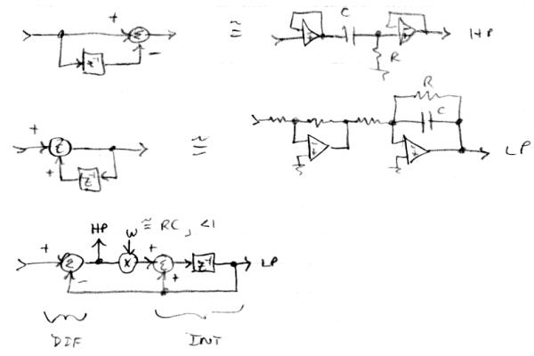
I can try!  Here's a sketch of some rough digital / analog equivalents:


At top is a differentiator, digital on left, analog on right.  The circle is an add, the box with "z^-1" delays the input number by a single clock.  So if we input 3, and on the next clock 5, what gets output on that clock is 5 - 3 = 2.  The analog version clearly has a bleed resistor, which forms an RC time constant, but if the input is changing significantly faster than RC then you get a differentiation action that is similar to the digital version.

In the center is an integrator,digital on left, analog on right.  If the input again is 3, and then 5, we get 3 + 5 = 8 output on that clock.  The analog version has a bleed resistor, which makes the output follow the input over the long term, but gives summation in the short term.

At the bottom is a combination of digital differentiator and integrator in a feedback loop, which yields a first order digital filter.  This is more analogous to the analog differentiator and integrator because it has a true time constant as given by w (omega) which is a number less than one.  Notice that IN - LP = HP which is how analog filters work too.  It's probably easiest to see how this works in Excel, but you can do a small simulation of it on paper too.

If you differentiate then you get what I was doing for velocity.  I think you're using an analog differentiator, which is more of a digital high pass filter.  I was also forcing negative results of differentiation to zero, whereas you aren't.

I'm still on the fence as to what to do here and it's got me kinda stuck.  I can do a lot of what you show in your video, but not all, and I'm thinking a lot of it comes down to non-linearity and / or analog hitting limits.  And I suppose I'm somewhat biased having played it for a while, but having a definite threshold seems to make it more controllable when mixing regular playing and percussive playing.  But you really show a lot of control in your video so it's still something of a mystery to me.

"Can users (easily) build their own sounds with your theremin? A broad field."

Yes, within the framework of the fixed DSP datapath and the parameters controlling the elements (all knob parameters are part of the preset system).  It's a small virtual analog synth with emphasis on vocals.  I'd like to get an OK violin family sound from it, but emulating existing analog Theremin sounds has become less important to me.

Posted: 4/15/2018 2:19:23 PM
DOMINIK

From: germany, kiel

Joined: 5/10/2007

Thanks for your explanations! I didn't get it all but at least i did some research about some basics.. but still have to keep on, in order to understand what i have found per chance / experimentation..

Violin family sounds good. A raspy celloesque timbre with a little reverb (to get the body) is one favorite for me.

Posted: 4/16/2018 9:33:48 AM
pagehamilton

Joined: 8/25/2014

hi

I'm based in London and looking for a theremin player to record some brief parts for a song i'm doing. Are you interested in having a go? We can correspond a bit and ill answer any questions you might have. Thanks   

Posted: 4/23/2018 2:45:09 PM
dewster

From: Northern NJ, USA

Joined: 2/17/2012

Domink: I imagine the VCA in the Subscope is linear?  If so, then the velocity sensing is in the exponential domain.  My prototype does velocity sensing in the linear domain, which could explain much of the difference between the responses of our Theremins.  This is something I need to explore.

[EDIT] Never mind, I just graphed this in Excel and it doesn't appear to be a factor.  (I encountered exactly this sort of thing in grad school, where we were doing math on a CO2 sensor.  The biology engineering prof. on the team whipped out some graphs that showed there was almost no difference between the function of a small difference and the small difference of a function.)

Posted: 4/24/2018 2:26:08 PM
dewster

From: Northern NJ, USA

Joined: 2/17/2012

Electro-Harmonix Talking Machine Formants

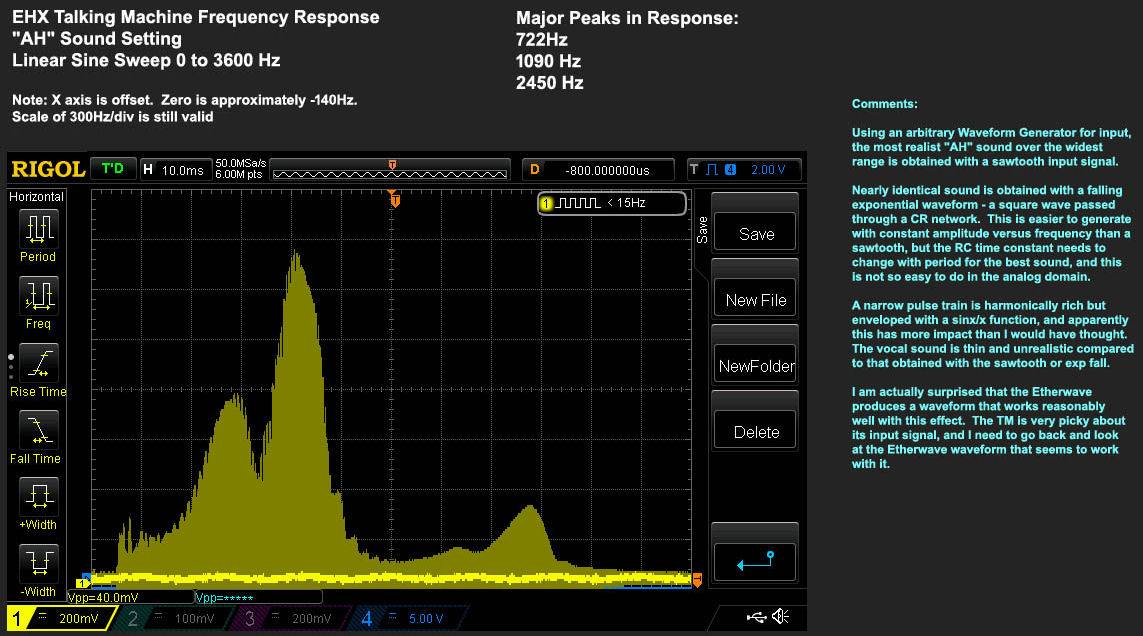
A kind and generous TW member who hasn't posted here yet sent me this sine wave sweep of the EH Talking Machine pedal:

Some comments regarding the sweep are included on the right.

I set the prototype to these formant frequencies and amplitudes, and added a small amplitude resonance around 2kHz, and another around 200Hz, just to fill things out a bit.  I haven't compared it directly to the TM recordings, but it definitely sounds like a tenor.  It doesn't do the AH - OO thing like Peter Pringle's videos, but that's probably some unknown processing going on and / or the influence of a pole in the source.  I intend to add articulation to several or all of the prototype formants, so I'll be able to at least approximate that behavior soon.

A huge "THANK YOU!" to our mystery member for this highly useful info!

Posted: 4/28/2018 6:23:58 PM
dewster

From: Northern NJ, USA

Joined: 2/17/2012

Progress Report : 2018-04-28

- For a while now have noticed here and there that twisting an encoder really fast would make it's value go the wrong way.  Turns out it's probably a hardware issue (a bad encoder). Wish I could buy higher quality ones without breaking the bank.  Seems they're either $0.80 or $10 with nothing in-between.  Need to test them for this somehow before soldering them to the board.

- While staring at the code I realized I'm truncating the noise and oscillator outputs to 16 bits, then jacking them up at the filter inputs 8 bits to provide "footroom" and then lopping them back to 16 bits before kicking them out via SPDIF.  I'm now truncating the sources to 24 bits and feeding that to the filters, so the "footroom" is now filled with real data.  24 bit data baby!

- Added amplitude modulation to the noise source, which uses the oscillator waveform for doing the AM.  Also limited the noise envelope drop range and made it higher resolution.  Both of these things make the onset of vocalization seem a bit more realistic.  And you can do steam trains and purring cats with the arrangement.

- Took another look at the hum filter.  The CIC now decimates by 16, which reduces the comb delay memory requirement by 16!  So I've got almost 1/2 of Hive main memory back.  Still looking at it, if it holds up it'll provide a lot of welcome coding room.

- Back to LOG2 velocity scaling.

=============

Ordered a ~$20 plastic box for possible antenna use.  Hasn't arrived yet.  The enclosure / superficial stuff will kill you.

Ordered another RAM ball joint thingie to look at - the type that has a "diamond button" on one end and ball on the other.  The octagonal button neck makes rotation too difficult and restrictive, unfortunately (they should have picked a polygon with more sides).

On the excellent suggestion of someone else, I ordered some 1" plastic ball knobs with M6 brass inserts to see if they might work as ball joints.  Quite inexpensive from Hong Kong.  Haven't arrived yet.

Gotta get serious about the audio aliasing issue, rearrange the UI screens, start PWB layout, etc.

=============

Say aah!  (MP3)

Posted: 5/4/2018 5:58:34 PM
dewster

From: Northern NJ, USA

Joined: 2/17/2012

Anti-aliasing Oscillators

Stumbled across this very nice summary of anti-aliasing oscillator techniques:

https://edoc.site/antiasliasing-osc-algoritmsubtractive-synth-pdf-free.html

BLIT and BLEP are shown, as is DPW.  DPW uses analytic (numeric) integration of a naive sawtooth followed by signal type differentiation.  It's fascinating and looks really promising, and doesn't require fancy gating, but has subtle scaling and gain issues.  Look up other papers by Välimäki for the details (as in all things research paper, sci-hub is your friend).

I was thinking a CIC interpolator followed by a CIC decimator might natively anti-alias, but haven't been able to work through that as the first order case seems to devolve into a trivial solution.

Now I'm thinking, since my PM-based oscillator has a brightness control, and I don't hear aliasing until it hits around 1kHz or so, it might be easiest to just start tapering the harmonic content off via the brightness control when the fundamental goes above ~1kHz, until it's just doing a sine at the max of ~8kHz.

One paper I read said harmonics that alias below the fundamental are the most audible, which makes sense.  With my own generator I don't hear them until they reach an amplitude of -48dB or so of the fundamental, and the ones below the fundamental really jump out at you.  There's an analytic masking function for it (i.e. things your ear can't hear).

[EDIT] More in-depth: "Filter-Based Oscillator Algorithms for Virtual Analog Synthesis" by Jussi Pekonen

And "Antialiasing Oscillators in Subtractive Synthesis" by Vesa Välimäki and Antti Huovilainen is worth a search.  (Sad / ironic how much useful science is stuck behind paywalls.)

You must be logged in to post a reply. Please log in or register for a new account.