Let's Design and Build a (mostly) Digital Theremin!

Posted: 1/18/2019 12:50:19 AM
dewster

From: Northern NJ, USA

Joined: 2/17/2012

LOUDNESS!

Here's the analog loudness circuit from the article I pointed to yesterday:


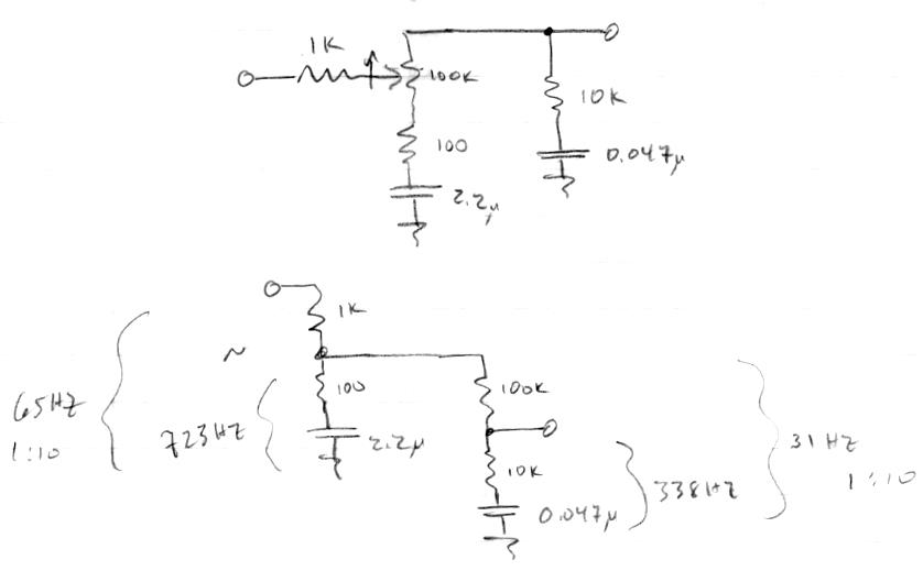
At top is the fairly clever circuit.  Clearly, when the pot wiper is fully clockwise it's pretty much just a wire.  At bottom is the equivalent circuit when the pot wiper is fully counter-clockwise and maximally "doing it's thing".  Several things to note here: 

1. It's a cascade of two first order low pass filters that can be considered to be isolated due to the 1:10:100 impedances.
2. The dual resistive dividers each individually limit the treble cut to 1:10 for a total of 1:100 or -40dB.
3. The treble cut limiting is a "shelving" action, so above some frequency the signal levels out.
4. The -3dB cutoffs are at 65Hz and 31Hz, so signals roughly below 31Hz aren't attenuated.
5. The shelving points are 723Hz and 338Hz, so signals roughly above 723Hz are leveling out.

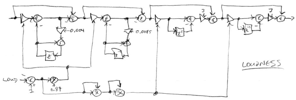
How to implement this digitally?  Zölzer's book shows ways to use all-pass filters with feed-forward to create low and high pass filters, and mixing the filter input with the filter output creates a shelving filter.  There are ways to use feed-back for cut, but they're hampered by the need for a delay (in order to be "causal") which messes with the response at the extremes.  So feed-forward is the way to go here, and it conveniently gives us a [0:1) range cut input parameter.  There's no need to implement the high pass filters as all-pass, I believe that's just a unifying concept in Zölzer's chapter, so we'll use the normal high/low pass construct.  As in the analog case, we need to cascade two shelving high cut filters in order to obtain a wide enough range and steep enough attenuation:


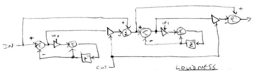
The cut input sense is reversed via the logical NOT operation so CW/CCW gives more/less treble, much like a conventional level control.  And since there are two such attenuations in series, it seems a linear taper feels OK as the result is rather equivalent to a squared taper.  The cut input is limited to 0.9 via extended multiplication (not shown here) so as to limit treble cut to -40dB.  The construct is capable of doing a bit more than this but it gets pretty muddy down there.  The frequency determining multiplications w0 and w1 are 0.004 and 0.0085 for -3dB @ 30.61Hz and 65.21Hz respectively, same as the analog case.

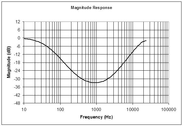
Here's the calculated response (Excel) when fully engaged:

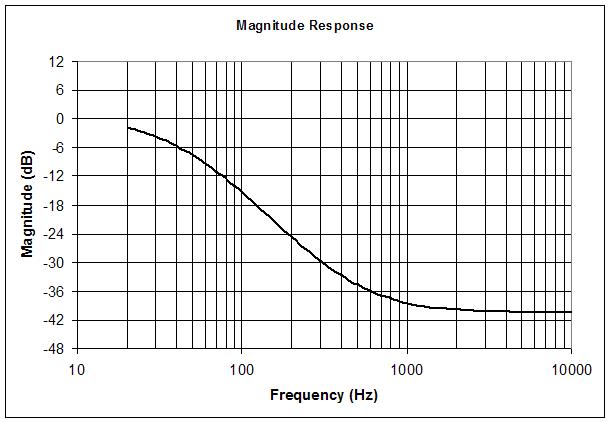
I've confirmed the above response on the prototype.  Indeed, turning the loudness knob CCW lowers the overall volume without thinning out the bass. 

Another audio / DSP mystery (for me, anyway) solved!

Posted: 1/23/2019 12:05:38 AM
dewster

From: Northern NJ, USA

Joined: 2/17/2012

One Louder

That upward tilt of the treble end of the loudness graph was bugging me, and lots of loudness cut sounded muffled to me, so I decided to add some treble boost.  Tried first order, but it seems to need second order to these old ears.  Two shelving differentiators later and it seems to be working a little better.  I also moved the mixing attenuation to before the filters rather than after to help with overload.  Here's the curve at maximum cut:

And here's a sample you can listen to: [MP3].  The first 4 riffs are identical, the first at full volume, the second -6dB, the third -14dB, the fourth -28dB, with the attenuations performed manually after the fact in Audition. The next series is the first riff again (with loudness knob set to 63, or defeated), followed by the loudness knob being set to 43, 23, and 3.  So, first 4 are turning down the volume, the second 4 are turning down the loudness.  To do it justice you should "calibrate" your setup to make the very last riff sound fairly balanced in tone.

[EDIT] I tweaked the treble boost calculation a bit and updated the graph above.  Regardless of what that article says, I believe you really want some treble boost along with bass boost when scooping out the midrange.

[EDIT2] Here's the final design:

Posted: 1/27/2019 4:13:24 PM
dewster

From: Northern NJ, USA

Joined: 2/17/2012

It Goes Straight To Math...

Inspired by the woodwind and brass samples at this site [LINK] I'm kinda sorta looking into physical modeling / waveguide synthesis lately.  They employ variable multi-clock delays, often tapped, which are fundamentally difficult to implement.  For one thing the delay period is the inverse of the frequency you want it to operate at, so there's that dreaded inverse to deal with.  For a second thing it's rather tricky to generate sub-clock delays that don't give inharmonic upper partials or frequency response issues.  For a third thing it seems that it's really difficult to do glissandos and the like without glitching, energy issues, or aliasing entering the picture.  Fourth, they consume precious memory, which I'm rather low on lately.  So I'm having a hard time warming up to it all because it's such a can of worms.

I ran across this paper, which I actually read a long time ago:  https://quod.lib.umich.edu/i/icmc/bbp2372.1997.068/1  It's not all that common to encounter papers that tell you exactly how to solve practical problems.  Most go straight to the math and sometimes, almost in passing, give you hints as to the problem solution.  I know papers are written in order to further our understanding, and math is the tool to use here, but if basic concepts can be understood before the math then I believe that's the way they should be presented.  I imagine much of the math is done as after the fact proof rather than as the basis of inspiration or even understanding.

Anyway, that paper is pretty nice, and presents a couple of things I wanted to mention here:  

One seems quite central to implementing any variable delay, and that is to allocate some maximum power of 2 value (size = 2^m) of contiguous memory space for the delay, and always use it all, regardless of the delay setting.  The idea then is to have the write pointer step through the whole thing in a modulo manner, writing to address n, n+1, n+2, ..., n+m-1 and have "the read pointer chasing the write pointer" around like a reluctant dog on a leash, with the distance between them being the desired delay.  This minimizes delay time change glitching to some extent and gives you a lot of valid data to work with should you need to interpolate and the like to produce fractional delays at the read tap.

The second is the psycho-acoustic notion of Just Noticeable Difference (JND) for human pitch perception.  The worst / best case (depending on how you view it!) is the octave between 1kHz and 2kHz (~C6 to ~C7) where we as a species can resolve around 280 JNDs.  I assume these are exponentially spaced, so the ratio between JNDs is 1 - ((2kHz/1kHz)^(1/280)) = 0.0024786 or roughly 0.25%.  In music, a one cent ratio is 1 - (2^(1/1200)) = 0.0005778 or roughly 0.06%.  So one JND = 0.25/0.06 = 4.3 cents, worst case, which is a handy thing to know.  Before I encountered the JND I was using the value of 3 cents from something Don Lancaster published IIRC.

Posted: 1/28/2019 9:00:06 PM
dewster

From: Northern NJ, USA

Joined: 2/17/2012

LED Tuner Update

I went ahead and did a LED tuner full serialization mod today and it's currently working fine on my prototype.  I edited the FPGA SystemVerilog code to do this.  The mod reduces the number of sensitive info-carrying wires between the FPGA and tuner board from 6 to 4, which should be ideal for CAT5 interconnect as one can use the other side of each pair to carry ground or power while providing some shielding / isolation.  I avoided this configuration in the first place because I was afraid of data races between the devices (which I sidestepped completely by using 3 separate data lines providing data on the falling edge of the clock) but a series resistor is probably sufficient to slow down data changes and give adequate hold time.  The HW/SW interface is the same so there was no need for a new SW load after repumping the FPGA.  Here's the updated tuner schematic:

The hardware changes are all on the tuner board and they're pretty trivial:

1. Disconnect SDI0 and SDI1 from FPGA to tuner board going to IC0 and IC1 (pin 2).  SDI2 is the only serial data connection now, going to IC2 as it did before.
2. Connect SDO from IC2 (pin 14) to SDI on IC1 (pin 2) via 1k series resistor located close to SDO.
3. Connect SDO from IC1 (pin 14) to SDI on IC0 (pin 2) via 1k series resistor located close to SDO.

While I was at it I went ahead and changed the three current set resistors from 3.3k to 4.7k to make the low end a bit dimmer.  I never use the brightest settings, and the dimmest setting was a bit too bright in a dark room.  I also upped the encoder debounce counter widths from 12 to 14 to give 4x the debounce time constant (you have to use every counter-measure known to mankind in order to tame these cheesy things).

Posted: 1/29/2019 2:14:29 AM
oldtemecula

From: 60 Miles North of San Diego, CA

Joined: 10/1/2014

I apologize if I am off base

Most theremin interest is in playing or building, not following years of technical gibberish.

TW will die from lack of creative new ideas from others if this continues.

I will step away for another month, again, out of respect as to not interfere.

Christopher

Posted: 1/29/2019 4:38:22 AM
Jason

From: Hillsborough, NC (USA)

Joined: 2/13/2005

Keep it classy folks or I’ll have to start locking posts

Posted: 1/29/2019 10:09:20 AM
pitts8rh

From: Minnesota USA

Joined: 11/27/2015

"I went ahead and did a LED tuner full serialization mod today and it's currently working fine on my prototype.  I edited the FPGA SystemVerilog code to do this.  The mod reduces the number of sensitive info-carrying wires between the FPGA and tuner board from 6 to 4, which should be ideal for CAT5 interconnect as one can use the other side of each pair to carry ground or power while providing some shielding / isolation." [i]-Dewster[/i]

I want to make these mods on my prototype this week. So what would you think about implementing this by giving SDI and CLK dedicated CAT5 twisted pairs with LE and OE each being paired with the GND and 5V lines (acting as signal ground)?  This single-ended drive in a high noise environment is not ideal, but I'm thinking that SDI and CLK are more critical? It would be nice if this change takes care of the erratic behavior with different cables without having to resort to using stiffer shielded STP CAT5 cable or true differential data transmission.

As I continue to use it I find that I'm getting really attached to the idea of this tuner, despite my earlier skepticism, and I won't be giving it up now.  It will never take the place of pitch preview for me, but it is turning out to be useful for many other things including ear-training and staying referenced to standard pitches, and even for getting some visual indication of the level of RF environmental noise.

"While I was at it I went ahead and changed the three current set resistors from 3.3k to 4.7k to make the low end a bit dimmer.  I never use the brightest settings, and the dimmest setting was a bit too bright in a dark room."

Ha! Just earlier in the week I had changed the current set on R2 to about 1.5K to bring up the 7-segment brightness more in line with the 10mm LEDs.  But reducing the other currents instead makes more sense. At full brightness you can get retinal burns from those white ones. Although because I have changed to an apparently less-efficient red 7-segment (for sharper visual focus at a distance) I think it still needs more current than the others for good balance. 

BTW, have you ever tried the yellow LEDs from that assortment?  Mine seem really lame compared to all the other colors, almost to the point of looking like a bad batch.  Maybe I should increase the current to destruction to see what it can do.

Posted: 1/29/2019 5:11:32 PM
dewster

From: Northern NJ, USA

Joined: 2/17/2012

"I want to make these mods on my prototype this week. So what would you think about implementing this by giving SDI and CLK dedicated CAT5 twisted pairs with LE and OE each being paired with the GND and 5V lines (acting as signal ground)?  This single-ended drive in a high noise environment is not ideal, but I'm thinking that SDI and CLK are more critical? It would be nice if this change takes care of the erratic behavior with different cables without having to resort to using stiffer shielded STP CAT5 cable or true differential data transmission."  - pitts8rh

SDI is async, and I believe OE is too (the ICs seem designed after-the-fact to shoehorn in multi-mode), so my thinking would be to pair these up with 5V and ground that power the tuner board.  If I were feeling super persnickety, I'd maybe pair SDI with 5V and OE with ground.

CLK is definitely sync, and LE is a transparent latch, so I'd pair these with ground, but terminate them only on the FPGA (source) side, and leave them open on the tuner side (so currents aren't flowing in the shield, and to prevent ground loops).

"As I continue to use it I find that I'm getting really attached to the idea of this tuner, despite my earlier skepticism, and I won't be giving it up now.  It will never take the place of pitch preview for me, but it is turning out to be useful for many other things including ear-training and staying referenced to standard pitches, and even for getting some visual indication of the level of RF environmental noise."

Aha!  A convert! (of sorts) :-)

"Ha! Just earlier in the week I had changed the current set on R2 to about 1.5K to bring up the 7-segment brightness more in line with the 10mm LEDs.  But reducing the other currents instead makes more sense. At full brightness you can get retinal burns from those white ones. Although because I have changed to an apparently less-efficient red 7-segment (for sharper visual focus at a distance) I think it still needs more current than the others for good balance."

My 7 segment is dimmer too, it would probably be best to assign it its own driver IC, or do some kind of sub-PWM, in order to even up the brightness, but then again I barely use the octave display, so it's kinda low priority for me personally.  Hard to find displays that provide the same brightness / efficiency as single LEDs for some reason.

Side note: It's right at the edge, but a RED 7-segment with two series LEDs per segment should work off the 5V supply and still current regulate.  Using red LEDs for the note circle would also allow the center LED to be a common series element, which would completely isolate the 7-segment drive to one IC.

"BTW, have you ever tried the yellow LEDs from that assortment?  Mine seem really lame compared to all the other colors, almost to the point of looking like a bad batch.  Maybe I should increase the current to destruction to see what it can do."

Yeah, the yellow ones I got were pretty anemic too.  I picked the tuner colors mainly based on the brightness of the colors in that assortment, white was the brightest, blue a close second.

Posted: 1/30/2019 1:53:08 PM
dewster

From: Northern NJ, USA

Joined: 2/17/2012

"Keep it classy folks or I’ll have to start locking posts"  - Jason

Thank you Jason!  I'm very sorry you had to get involved, but the bullying needs to stop.

Posted: 2/5/2019 6:44:23 PM
dewster

From: Northern NJ, USA

Joined: 2/17/2012

Another Day, Another Coil

A couple of days ago I wound an 8mH air core single layer solenoid for testing purposes.  The form is 1.5 (48.26mm OD) schedule 40 PVC cut to 100mm long, with the windings 30mm from one end.  I used some 38AWG (0.113mm OD!) single coat that I had laying around from my long ago guitar building days (was going to wind my own electric guitar pickup but never did).  533 turns gives a coil height of about 60mm and a calculated DCR of 168 ohms.  As usual I used wire wrap wire for the interconnect, affixed the ends with nail polish, and encased the outside in heat shrink:

Actual measured L = 8.24mH, DCR = 183 ohms.

I started winding near the bottom, where you see some gaps, doing 20 or so winds at a time and then pushing them together.  Finally got the hang of it about 1/2 way through, and you can see the upper windings are much tighter and uniform.  AWG38 is kind of a harsh mistress, I don't think I'd want to make these babies in any quantity, it's like winding metal human hair.

When I stuck it on the pitch side of my D-Lev prototype it resonated at 471kHz.  I've since removed it and so it is now sitting on my bench doing nothing.

=============

Roger and I have noticed some fluttering in the pitch far-field.  For the longest time I just assumed it was LED tuner interference, but I narrowed it down to what I believe is the FPGA core / IO ring voltage fluctuation indirectly influencing the operating points of the axis DPLLs via phase modulation.  The fluctuation is easily observable via a diagnostic software load (which outputs the high pass filtered operating point as SPDIF audio) as a moving "hump" in the FFT, which is directly correlated with the audio pitch being played by the synth section - even when no audio makes it to any pin on the FPGA!  I'm mulling over the options, the AFE may need a redesign in order to isolate the interconnect levels and such.  The thing is entirely playable as-is, but I'd like to eliminate this effect if at all possible, or at least knock it down some dB.

You must be logged in to post a reply. Please log in or register for a new account.