Let's Design and Build a (mostly) Digital Theremin!

Posted: 2/6/2019 12:35:11 AM
pitts8rh

From: Minnesota USA

Joined: 11/27/2015

Pitch and Volume Latency Tests

I don't know if this is what you are looking for, Eric, but I still have the test setup ready if you want to request something else.  I sort of forgot what the point of this was except to confirm our previous volume latency guesstimates...

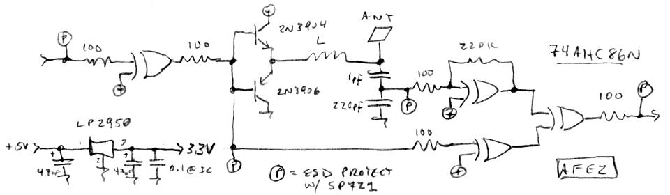
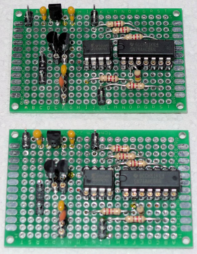
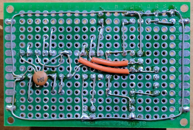
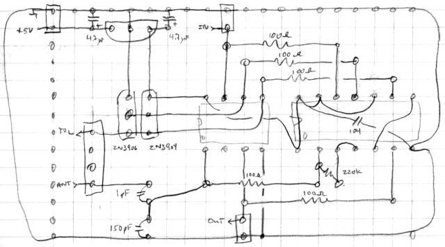
In order to simulate rapid hand movements on the pitch and volume antennas, I made a new board with a microwave relay that switched between two banks of pin sockets populated with paralleled fixed and/or variable capacitors.  The D-Lev was calibrated with the normal antennas, then one antenna (whichever side was being tested) was removed and replaced by the relay switched to the minimum capacitance position.  The capacitance for that side was adjusted to give nearly the same condition as with the normal antenna (either near-zero beat on the pitch or full-volume on the volume side).  Then the relay was energized to switch in the larger capacitance, which was then also adjusted to simulate a near-hand raised pitch or reduced volume.  This is different from the previous test in that this time an effort was made to select two switched capacitances that would give reasonable pitch or volume jumps (which turned out to be a little over an octave pitch, and about 36db volume).

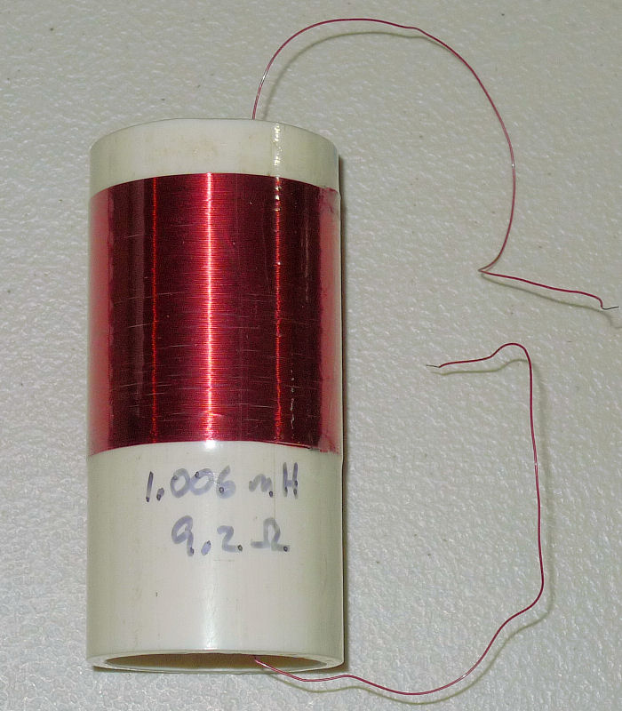
Even without the antennas on the theremin this is a pretty twitchy test to run, and that's why my one-octave goal turned out to be 13 semitones, and the volume shift was set up to go from one fully lit volume LED to all four fully lit.  The capacitance values are shown on the plots to be 1 and 3pf, but that only represents the values plugged into the test board.  There were other parasitics and intentionally-placed metal objects near both the high- a low-capacitance sides of the test board to fine tune the two states.

I ran this using your FPGA load with the adjustable pitch and volume bandwidths, p_bw and v_bw.  Before testing, I had been playing the theremin a bit and I wasn't sure that I could feel or hear any difference between the max and min pitch bandwidths, even with rapid trills.  The volume bandwidth effect was of course a lot more noticeable.

Unfortunately I didn't have a better way of displaying pitch shift that I could overlay with the switching waveform, so these just show the sine wave and you have to look at the wave periods to imagine what the pitch response curve would look like.  The first plot is the fastest pitch response with the bandwidth set to 4185.  I would say this is within 10ms:

And this is the other extreme with the pitch bandwidth set to 16, resulting in something more like 40ms to settle out:

Even though it is difficult to see where the higher pitch actually settles out, I did notice that the p_vbw setting had no noticeable effect until I got down into the 300Hz range.

By accident I had some intermittent contact on one of the capacitor sockets for some time that was allowing a pitch jump of a little more than 3 octaves, and during this time running the bandwidth control from max to min resulted in a barely perceptible change in this larger pitch jump, with the 16Hz setting producing a very slight portamento tail.  This was impressive because this represents a slew rate that is probably not humanly possible to achieve, and yet the pitch keeps up.  My impression is that if you couldn't A-B compare the performance with between max and min bandwidths, you wouldn't be able to tell a difference while playing.  The upside of keeping the pitch bandwidth low is that the extremely far field pitch noise is reduced, not so much because you hear it but because you can see it on the tuner.

The volume response tests were run the same way as the pitch tests, although the high and low capacitances were optimized to obtain a range that went from full volume to barely perceptible.  Here of course it is much easier to see the response times.  Plots for three bandwidths are shown; the two extremes of 16Hz and 4185Hz, and one at 202Hz where the volume response is clearly affected.  There seemed to be no visible effect on latency until the bandwidth was reduced to about 550Hz.

Here are the three volume response plots at BW=4185Hz, 202Hz, and 16Hz:

With the volume bandwidth set anywhere in the range of 4185Hz down to 550Hz the full-amplitude volume latency stays within the golden 10ms limit.  I don't know if there are any compelling reasons to limit the volume bandwidth, but I would like to see it kept as wide open as possible.  I would think that the pitch bandwidth could be kept low, maybe even at 16Hz. Worst case, some fast trills might require a little more finger movement, but I don't really feel any sluggishness as you would with volume latency.

[EDIT] I'm going to take back those last two sentences.  After playing some more with the pitch bandwidth set at both extremes it does seem that trills take a little more effort and are less responsive at v_bw=16.  I tried increasing the bandwidth while watching for the setting where the far-field noise increases on the tuner, and the point at which trills become less inhibited unfortunately occurs where the noise filtering is minimal.  If these bandwidth controls (or maybe just p_bw) could be left in permanently or at least for a while we may be able to come to a better answer on this.

Posted: 2/6/2019 5:12:58 PM
dewster

From: Northern NJ, USA

Joined: 2/17/2012

Roger, thank you so much for spending the time and effort to do these tests!

"I sort of forgot what the point of this was except to confirm our previous volume latency guesstimates..."

Mainly to investigate the (and by "the" I mean "your" :-) subjective sense of what minimum bandwidths are sufficiently transparent to the user during play.  As you know, there is the eternal and iron trade-off between bandwidth and SNR, so the bandwidths shouldn't be set higher than necessary, and they shouldn't be set too low either, creating a Goldilocks zone.

"Even though it is difficult to see where the higher pitch actually settles out, I did notice that the p_vbw setting had no noticeable effect until I got down into the 300Hz range."

"There seemed to be no visible effect on latency until the bandwidth was reduced to about 550Hz."

This is due to the upstream filtering going on in the LC DPLLs (which act as first order low pass filters for phase noise), and the third order anti-aliasing filter which is used for rate conversion down to the 48kHz PCM sampling rate.  These HW cutoff frequencies are 365Hz for the pitch axis and 537Hz for the volume axis in the FPGA load you're testing with, which is pretty much what you measured with your setup.

"After playing some more with the pitch bandwidth set at both extremes it does seem that trills take a little more effort and are less responsive at v_bw=16.  I tried increasing the bandwidth while watching for the setting where the far-field noise increases on the tuner, and the point at which trills become less inhibited unfortunately occurs where the noise filtering is minimal.  If these bandwidth controls (or maybe just p_bw) could be left in permanently or at least for a while we may be able to come to a better answer on this."

I have no objection to leaving them in for as long as necessary as this is a fundamental thing that I'd love to have resolved or at least somewhat contained.  I don't think I'd feel comfortable with setting it permanently below 100Hz or so for the pitch side, if only for advertisement purposes! :-)  To kill hum most effectively with the 6x notch filters I've got in there now, the 4th order filters you're manipulating should both be set to roughly around 300Hz (for 60Hz mains; 250Hz for 50Hz mains).

Over the past week or so I've modified the FPGA anti-alias (AA) filter to be 4th order and to sample every other clock, so as to ease the FPGA build timing closure bottleneck, and to make these filters wider and more optimal in terms of truncation noise.  I'm doing everything I can to make the axis filtering "blameless" in terms of alias and noise artifacts.  With the 4th order AA it's possible to leave the HW side bandwidth somewhat wider and then torque it down later in SW, where filtering is cheaper and more exact.

It's interesting that the pitch axis bandwidth can perhaps be quite a bit lower than the volume axis.  If it seems that the volume axis needs more than 300Hz bandwidth I could modify the hum filter to make it squash more harmonics.

Posted: 2/10/2019 4:35:34 PM
dewster

From: Northern NJ, USA

Joined: 2/17/2012

The Call Is Coming From Inside The House

I'm looking more closely at the far field flutter and the mysterious moving hump that tracks audio pitch.  There is a peak in the FFT and clear cyclic behavior in the waveform around 12Hz, which coincidentally (or not) is the LCD and encoder update rate.  My options here are:

1. Smear the peak via spread spectrum.
2. Stick another notch filter there.
3. Update the LCD only when encoder values or screen values change.

#1 doesn't reduce the noise, only spreads it out.  #2 might place the lower notch filter skirt really close to DC.  #3 would generate more impulsive noise during the LCD screen update.  #2 is trivial to implement but consumes real-time.  I'm leaning towards #3 but have to look into it more fully.

Meanwhile, I have a theory for what is causing the mysterious moving hump.  I posit that the FPGA itself is perturbing the capacitance field, rather than some clock or level leakage in the FPGA core, or level shifting at the FPGA pins.  I could stick yet another in-line notch filter in there to smash it, but the tuning of the filter couldn't be fixed, but instead would have to follow the audio pitch.  This is a bit of a chicken / egg situation as the thing that's being filtered is the thing setting the filter notch location.  I'm wondering if I could instead use a variable low pass filter here to "adaptively filter" the far field, which has the potential to kill a whole lot of birds with one stone.

Posted: 2/12/2019 2:06:42 PM
tinkeringdude

From: Germany

Joined: 8/30/2014

Haven't paid attention for a while, trying to catch up:
The hum filter a few pages back - hey, kindly don't forget the Europeans with 50 Hz option 

Btw., why do do you use wire wrap wire for your coil ends?

As for 12 Hz notch: What speaker reproduces 12 Hz?
Except those turbine like fans with angle-adjustable blades and big wood cabinet around (this is by far not the biggest / sturdiest setup I've seen, it's for quasi-lunatics who wish to have some extraordinary home cinema experience I guess):

Will this have negative impact, audibly, with normal instrument speakers? Well if so, could you instead use an analog high-pass at the end of the chain which starts to cut off everything from 30Hz or so downwards? (I don't know how much those 12 Hz move around)

Posted: 2/12/2019 2:22:30 PM
dewster

From: Northern NJ, USA

Joined: 2/17/2012

"The hum filter a few pages back - hey, kindly don't forget the Europeans with 50 Hz option"  - tinkeringdude

I've got you covered!  There's a system level option to switch the notch filter bank between 60Hz and 50Hz mains frequency harmonics.

"Btw., why do do you use wire wrap wire for your coil ends?"

No huge reason.  But it's flexible, easy to solder, and I have a bunch just laying around.

"As for 12 Hz notch: What speaker reproduces 12 Hz?

Will this have negative impact, audibly, with normal instrument speakers? Well if so, could you instead use an analog high-pass at the end of the chain which starts to cut off everything from 30Hz or so downwards? (I don't know how much those 12 Hz move around)"

It's a warble in the control number feeding the oscillator and filters, so it has to be good down to DC.  Very analogous to adding vibrato with your hand at a certain position, you can't high pass filter it without losing the hand position.  Though you could notch filter it, or stop fluttering your hand (remove the source).  I'm going to look into the latter today.

Posted: 2/12/2019 5:03:05 PM
dewster

From: Northern NJ, USA

Joined: 2/17/2012

AM Radio Testing

Since the D-Lev volume and pitch oscillators currently fall smack dab in the US 540kHz - 1600kHz AM broadcast band (or should I say the AM band falls smack dab in prime digital Theremin operating territory) I thought I'd quickly check out their unintentional radiation.  So I tuned my home stereo to first 1040kHz and then 600kHz, and fully expected to hear squealing when I "tuned" the axes by moving my hand near the plate antennas, but all I heard was a fairly low level "hash" sound.   It seems the LC DPLL pseudo-random dither, necessary to dramatically increase SFDR (spurious free dynamic range) and kill sticky spots in the fields, is doing a spread spectrum job on the emitted RF.  This seems like a good thing, as a bit of hash is probably less objectionable than a squeal for those unfortunates on the receiving end of this business.

I've often thought it would be really spiffy to psuedo-randomly switch capacitors / coils in and out of the LC tank at the crossover point, thus maintaining the high Q voltage swing over a really wide swath of frequencies, smearing the peak RF down to almost nothing.  This might enable many axes to operate in close proximity without interference, perhaps by using orthogonal Gold codes rather than separate discrete frequencies.

Posted: 2/12/2019 7:50:57 PM
dewster

From: Northern NJ, USA

Joined: 2/17/2012

AFE2

The original AFE (analog front end) was designed back when I wasn't all that sure what the final oscillator would end up looking like.  The FPGA sends a square drive signal to the AFE, and the AFE sends back square in-phase and quadrature signals.  This arrangement works fine, but needlessly exposes sensitive relative timing signals to long cable runs, and requires three interface signals.

Now that the FPGA firmware and assembly software aspects of the oscillators have calmed down (for now!) it seemed a good time to re-address the AFE.  Which I have, et voila!

It's more or less the old AFE but it uses XOR gates instead of inverters, implements a local XOR phase detector, and the logic family is AHC instead of LVU. One weird thing about AHC is that the inputs have hysteresis to improve the noise margin, but this will give you an instant oscillator if you have a bit of negative feedback and some input capacitance, not exactly what we want when buffering the capacitive divider!  Fortunately, the signal at the divider seems big enough not to be disturbed by this, and the hysteresis may be improving the centering of the threshold voltage at Vcc/2 as that seems better than the LVU inverters I've used (or maybe it's just chance).

With the old AFE the capacitive divider was set to a 1:150 ratio in order to contain the voltage swing into the buffer.  With the AFE2 I had to increase the ratio to 1:220 to give 3V peak-to-peak, which means the antenna is swinging over 600Vp-p with a measly 2Vp-p drive!  Since the coils I use are really high Q, they are quite sensitive to phase error.  I believe the local XOR detector may be reducing this error, thus allowing the DPLL to hit resonance more exactly.

I've currently got the AFE2 running on a breadboard and wired into the pitch side, with the parts necessary to better mount it on vector board arriving sometime later this week.  It's working like a champ, but I guess we'll see how it behaves once correctly mounted, given ESD protection, and over the longer term.  I modified the FPGA code to accommodate it, with build switches to select AFE or AFE2.  AFE2 only requires one DDR input, so cabling is reduced from 3 to 2 tender interconnect signals with absolutely no important relative timing between them (the phase information is conveyed via the duty cycle produced by the XOR phase detector).

==============

Another Day...

Just wound another coil:


It's 175 turns of 30AWG single coat on a 1.5 (48.26mm OD) schedule 40 PVC section of pipe cut to 100mm long.  The windings start 10mm in and the coil section is roughly 49mm high, giving an aspect ratio of 1.  It measures 1.006mH with a DCR of 9.2 Ohms.  I'm thinking of pairing this with a 4mH coil for the axes to give 700kHz / 1.4MHz operation, not sure which will go where.

Winding AWG30 is like falling off a log.  It took all of 4 minutes to do 175 turns, including tidying up here and there.

EDIT - Oops, I used AWG30, not AWG32, fixed it.

Posted: 2/15/2019 12:48:58 AM
dewster

From: Northern NJ, USA

Joined: 2/17/2012

AFE2 - Continued

The parts I ordered from DigiKey came super fast as usual yesterday.  People who live near Thief River Falls, MN must get the package before they click the "BUY" button!  And USPS first class shipping is quick too, as well as quite reasonable.  So I laid out and assembled the AFE2 boards, just finished up a couple of hours ago and they're now up and running.  Here are some pix:


The two AFE2 boards.  I used a slightly smaller vector board this time.  These are really nice plated through vector boards - never use those crappy phenolic ones like Radio Shack used to sell, the foil peels off if you just think about soldering them.  The sockets are DIY, single socket strip material snipped to length - why buy and personally stock custom expensive sockets?  And DIPs are just about gone...  I ran out of 100 Ohm resistors so used 120 Ohm here.


Here's the back of one of the boards.  Ground runs around the outside (ground loop!), the quad XOR is decoupled, all outer connecting pins are ground for easy remembering / consistency at hookup time.  The first board took me maybe 6 hours to assemble, the second maybe 4 as copying is easier than figuring.  I wire really slow but fairly sure.


Here's a top view of the layout and wiring.  I decided to locate the 1pF on board this time rather than have it hanging in space between the antenna plate and the AFE.  I used a 4x pin block with the two inner pins snipped off to make a good solderable anchor without too much stray C.  I like the layout, it's cleaner and a bit more compact than the previous AFE.  And this time I ran ESD protection to just about everything I could think of, with one protector left over.

After removing the old AFEs and installing the AFE2s I modified the FPGA code to also use AFE2 on the volume axis, recompiled, and the performance seems solid.  I ended up again using 150pF in the C divider, I suspect the coils are still too close to the plates, looking like a distant shorted winding, causing some Q loss.

What do others here do to remove flux?  I usually scrub with an old toothbrush using first alcohol and then water, but it never gets it all off, leaving the thing rather gooey all over.  This time I followed up with really hot water and some dishwashing soap, but there's still some flux.

Posted: 2/15/2019 10:03:01 AM
pitts8rh

From: Minnesota USA

Joined: 11/27/2015

Just in the nick of time!  I've been thinking about updating my prototype and I wanted to know your latest coil specs.  From a purely mechanical standpoint it might be preferable to keep the pitch oscillator frequency above that of the volume oscillator, if only for the reason that the pitch antenna is more likely to be on an extension arm where a smaller coil can in some cases simplify design (at least in one case near and dear to me!).  It's certainly not necessary though.

Regarding the potential for interference, I also looked at the pitch and volume emissions a couple days ago while trying both AM and FM demodulation, and the most I heard was either quieting or a rushing sound.  This surprised me too because you'll remember a while back I reported squealing heard on an AM car radio coming up the driveway.  At the time my pitch oscillator could easily have been right on top of the 830KHz that the radio was tuned to, so it's possible that this produced some audible difference tone.  It wasn't anything recognizable or even musical, but the same can be said for my direct audio output at times.

I'll make a thru-hole AFE2 pcb first along with a PVC coil to check everything out.  I still need to order parts and possibly some wire.  I could use your modified output.jic for this at some point too (still too overwhelmed to try doing this myself just yet).

Posted: 2/15/2019 1:55:41 PM
dewster

From: Northern NJ, USA

Joined: 2/17/2012

"I've been thinking about updating my prototype and I wanted to know your latest coil specs."  - pitts8rh

I screwed up in my penultimate post, I actually used AWG30 rather than AWG32 for that 1mH coil (fixed it).

I'm thinking of going with AWG32 for both coils and varying the former diameter to make the coil height more or less a fixed dimension, and damn the aspect ratio. This would allow one to space the business end farther from the plate, likely improving Q.  AWG32 is fine enough to not consume a ton of copper, but not so fine that it's difficult to handle or have high DCR.  But at this point most of this seems to be in the polishing / puttering around the edges / diminishing returns territory, because just about any half-way well made coil seems to work OK with the AFE.

One thing I really don't understand is the seemingly lower Q of higher frequency tanks.  A smaller L can easily have an order of magnitude lower DCR, so you would think it would be the other way around, even taking skin effect into account (as my spreadsheet does).  I don't think RF transmission can fully account for it, but perhaps it's a combination of slight phase error, RF emission, AC skin effect, digital dither, etc...  And of course there is the Q of the air / universe forming the tank C which is unknown to me.

"From a purely mechanical standpoint it might be preferable to keep the pitch oscillator frequency above that of the volume oscillator, if only for the reason that the pitch antenna is more likely to be on an extension arm where a smaller coil can in some cases simplify design (at least in one case near and dear to me!).  It's certainly not necessary though."

I might end up right there with you.  Keeping the pitch axis out of the AM broadcast band might make it more "blameless" and the most straightforward way to do this is 1mH volume / 0.5mH pitch.  I feel a bit better going to higher operating frequencies with the AFE2.

There is probably a simple formula floating around out there in the ether for how high one can practically go for the given effective FPGA pin clock resolution of ~400MHz.  The C divider ratio and the signal at it can provide an almost direct measure of overall tank Q, given the (square) drive of ~2Vp-p, but only if there were no dithering of the output edges.  The amplitude of the dither signal is one UI (unit interval) at the pin clock resolution, so a higher LC resonance will have more dither than low LC resonance, which smears out the resonance point more, forcing the LC to operate statistically farther to either side of resonance, thus effectively lowering LC Q.  An analogous way to look at it is a noisy square wave driving a resonant LC low pass filter - the more noise the less energy is available to drive resonance.

"Regarding the potential for interference, I also looked at the pitch and volume emissions a couple days ago while trying both AM and FM demodulation, and the most I heard was either quieting or a rushing sound.  This surprised me too because you'll remember a while back I reported squealing heard on an AM car radio coming up the driveway.  At the time my pitch oscillator could easily have been right on top of the 830KHz that the radio was tuned to, so it's possible that this produced some audible difference tone.  It wasn't anything recognizable or even musical, but the same can be said for my direct audio output at times."

Interesting, thanks!  I was trying to replicate your earlier report of major interference some distance away and couldn't.

You must be logged in to post a reply. Please log in or register for a new account.