Let's Design and Build a (mostly) Digital Theremin!

Posted: 5/1/2019 3:16:44 PM
pitts8rh

From: Minnesota USA

Joined: 11/27/2015

That's a pretty decent imitation of a dobro.  Does this have any inharmonic resonator added? It has that boxy stringed-instrument characteristic that you use in your violin-cello presets.

I suppose this would be nice for those that find a real dobro too trivial to play with those frets serving as a visual reference cheat.  Now if you can also come up with a 6-channel polyphonic D-Lev (like the "polyphonic" Etherwave) you'll have something.

Roger

Posted: 5/1/2019 10:16:15 PM
dewster

From: Northern NJ, USA

Joined: 2/17/2012

"That's a pretty decent imitation of a dobro.  Does this have any inharmonic resonator added? It has that boxy stringed-instrument characteristic that you use in your violin-cello presets."  - pitts8rh

Thanks!  Yes, it uses the resonator - rather aptly named for this particular voice!  The base sound is a male vocal, oddly enough.  One runs into all sorts of stuff twiddling knobs on any synth.

"I suppose this would be nice for those that find a real dobro too trivial to play with those frets serving as a visual reference cheat.  Now if you can also come up with a 6-channel polyphonic D-Lev (like the "polyphonic" Etherwave) you'll have something."

Ha ha!  Or make a spoof video of it - then I could have the (once) highest viewed TW thread by doing literally no R&D.

Posted: 5/2/2019 3:19:06 PM
dewster

From: Northern NJ, USA

Joined: 2/17/2012

Multi-Oscillator (final?)

Here's (what feels like) my final multi-oscillator (at least for now):


The base PM oscillator module was detailed in a recent post here: [LINK].  OSC0 and OSC1 share identical "harm" (with shared pmul & vmul axis modulation) and "hmul" controls, and are given variable additive offsets going in different directions via the "sprd" control and the star functional box - which is a negation and multiplication by a factor less than one but greater than 1/2.  I'm using the golden ratio minus one here, or 0.6180339887, which seems to give a long interbeating period between all three oscillators when mixed together.  OSC2 has a separate three plateau cubed multiplicative offset of +/- 1 octave at the extremes, and separate "harm" control (with separate pmul & vmul axis modulation).  The outputs of OSC0 and OSC1 are divided by 2 (not shown) and simply summed, and the output of OSC2 is crossfaded (with pmul & vmul axis modulation) with the OSC0 & OSC1 sum to produce the output.

I decided to have the main sound be the paired oscillators and the secondary the singular oscillator, which is opposite of what I had previously, as I believe the user would expect the "sprd" control to work right off the bat.  By making OSC0 and OSC1 share most knobs, the flexibility isn't significantly impacted, and it all fits on two UI pages.  Honestly, there isn't a ton of interesting and musically useful variation you can do with three oscillators in a fixed configuration like this.  And there's a nice division of labor here regarding the input offsets.

Also not shown is a sync method that aligns the relative phases of the phase accumulators across oscillators:
1. If (sprd == 0) then OSC1 is forced to have the same phase as OSC0, so their outputs are identical and they sum to a full output at their summer. 
2. If (sprd == 0) and (offs == 0) then OSC2 is forced to have the same phase as OSC0.
3. If (sprd == 0) and (offs == +max) then OSC2 is forced to have the same phase as OSC0 * 2.
4. If (sprd == 0) and (offs == -max) then OSC0 and OSC1 are forced to have the same phase as OSC2 * 2.

When turning the "sprd" and "offs" knobs, the forced sync conditions (when encountered via the above conditions) usually produce an instantaneous and noticeable change in timbre.  These transients can't be easily avoided, but the knobs probably aren't going to be tweaked much during actual performance (and if they are, maybe just avoid the sync condition settings), and it's necessary to have phase alignment when adding formants.  Presets in general shouldn't have random phase alignment between the elements.

Here's a sample of the interbeating, sounds like a crop duster to me (from the crop's perspective!): [MP3].  It's just 3 sawtooths and a bit of filtering.

Yesterday I remembered I had an old copy of Native Instruments FM8 on my PC, so I fired it up and played with it for the first time.  It has an interesting GUI when it comes to interconnecting the oscillators, but suffers from significant aliasing at higher modulation levels.  Anyway, it helped me to rather quickly rule out an idea I had, which was to use a common PM element feeding two separate and offset sine oscillators for beating - the result sounded just like AM, not what I was looking for.  IMO, the "sound" of FM8 relies heavily on multiple oscillator bank instances and stuff like chorus and other in-line delay effects.  Phase alignment happens during key-on events (when enabled within the various elements), something a Theremin doesn't have the luxury of.

Posted: 5/2/2019 9:46:24 PM
dewster

From: Northern NJ, USA

Joined: 2/17/2012

D-Lev Tour?

As readers know, there's been no lack of cabinetry noodling in this thread, but unfortunately without a lot to show for the effort expended.  While working on the oscillator (above) my thoughts returned to this, and I think I've got some ideas that might satisfy at least some players, as well as myself.  Here's a very rough sketch, not necessarily to scale or proportion, and which I've dubbed the D-Lev Tour (ala the t.VoX tour):


The emphasis here is on "tour" with a plywood (or similar) rounded corner case with a durable roll-on textured finish and plastic corner protectors like on amps and such.  The removable lid doubles as antenna storage.  The control panel is recessed lightly smoked Plexiglas, with the volume and pitch coils visible through it.  Alternatively, it could be back painted clear Plexiglas with masked openings for the tuner LEDs and LCD.  Antennas would attach via recessed UHF connectors or similar.  I think there would be enough clearance between the coils and the wood case to not have too much stray C.  Antenna geometry is TBD, but it could be anything from rods to paddles.

Thoughts?

Posted: 5/3/2019 10:04:38 AM
pitts8rh

From: Minnesota USA

Joined: 11/27/2015

Some thoughts on this:

Pros:
1) A roadie-case design could legitimately appeal to those who travel and value ruggedness and utility over aesthetics, and I mean that in a positive sense.

2) A box with rounded corners is about as easy to fabricate as it gets (except for the finish - see cons below).

3) Particularly for a road case, having the jacks on the player side is handy and hides the cable mess from audience view.

4) I interpret the inclusion of the inductors in the box and away from the antenna backside as a positive step forward in your thinking.  Having the coils inside the ends of a long box or at the ends of extension arms seems to be the right thing to do, and there haven't been any obvious problems with that approach on my prototype.

5) A carrying handle could be part of the detachable cover (assuming that you intended for the hinges to be the detachable type).

6) The corner mic-mount hole could actually be a slot to allow adjusting the slope (with a friction-adjustable female threaded socket)
 

Cons:
1) Even though this could be an attractive offering, I would not make this sort of design your flagship model due to the possibly limited appeal.

2) Painted plywood, even texture painted, is difficult to do well.  No amount of texture will conceal the box seams for very long, and even if the box is highly finished prior to painting the seams and plywood end-grain will eventually telegraph through the paint and look rough.  A box made of a high quality baltic birch with a textured skin (such as tolex to look like a guitar amp) would be more practical but would be more effort to fabricate in low quantities than something made from attractive solid hardwood.  You could still have a hybrid case made of nicely finished solid hardwood with the standard road-case hardware to protect it.

3) Assuming that the AFEs are inside the case, the antenna connectors could be any type of simple threaded or friction contact without introducing the bulk of an RF connector or something like the obvious plumbing fittings used on the Etherwave. 

4) I too would like to show off the coils through a panel, but this does suggest the need to internally finish the cabinet in visible areas.  For something like a tolex-covered box this would be some additional work; a solid hardwood box would be a little easier to clean up inside. If I did this I would have to pimp it out with some LED illumination on the coils of course.


Other thoughts:
1) In most cases a low-quantity build of this style of case would be accomplished by first building a completely enclosed box and then sawing it through lengthwise to created the separate lower case and lid.  Consider the possibility of making that cut at a slope, even going so far as to cut the corner of the box off at 45 degrees to create your sloping front while still maintaining flat-bottom case geometry.  I'm thinking of something like a sloped guitar amp head, with the cover held on with latches all around instead of latches and hinges.

2) I like back-printed clear acrylic for its appearance and protection of the graphics, but acrylic is pretty fragile to use for a road case.  You could certainly use polycarbonate instead. But cost-wise it may turn out that a custom self-adhesive matte-finish graphic panel may be cheaper than printing on the plastic panel itself.

3) A case style like this could be an attractive offering to some, as long as it is not the only choice available.  I think that calling it the D-Lev Tour suggests that offering this as one option is what you have in mind as well.

Just some random 4:00am ideas...

Posted: 5/3/2019 9:57:19 PM
dewster

From: Northern NJ, USA

Joined: 2/17/2012

"Pros:

4) I interpret the inclusion of the inductors in the box and away from the antenna backside as a positive step forward in your thinking.  Having the coils inside the ends of a long box or at the ends of extension arms seems to be the right thing to do, and there haven't been any obvious problems with that approach on my prototype."  - pitts8rh

Feels to me like a step back! :-)  Long-ish, heavy-ish box enclosing mostly air.

"5) A carrying handle could be part of the detachable cover (assuming that you intended for the hinges to be the detachable type)."

Yes, I should have included that in the sketch.

"6) The corner mic-mount hole could actually be a slot to allow adjusting the slope (with a friction-adjustable female threaded socket)"

Good idea!

"Cons:

2) Painted plywood, even texture painted, is difficult to do well.  No amount of texture will conceal the box seams for very long, and even if the box is highly finished prior to painting the seams and plywood end-grain will eventually telegraph through the paint and look rough.  A box made of a high quality baltic birch with a textured skin (such as tolex to look like a guitar amp) would be more practical but would be more effort to fabricate in low quantities than something made from attractive solid hardwood.  You could still have a hybrid case made of nicely finished solid hardwood with the standard road-case hardware to protect it."

I built a subwoofer out of flake board and covered in a water-based tolex-like crackle paint from parts-express (the paint I do not recommend!) of which the seams haven't shown through yet (several years now).  I put a couple of coats of sanding sealer on it first though.

"3) Assuming that the AFEs are inside the case, the antenna connectors could be any type of simple threaded or friction contact without introducing the bulk of an RF connector or something like the obvious plumbing fittings used on the Etherwave."

Yes, AFE's inside, dumb antennas outside.  I like UHF connectors because they are rugged, insulate the center conductor, and firmly lock at various selectable angles.

"4) I too would like to show off the coils through a panel, but this does suggest the need to internally finish the cabinet in visible areas.  For something like a tolex-covered box this would be some additional work; a solid hardwood box would be a little easier to clean up inside. If I did this I would have to pimp it out with some LED illumination on the coils of course."

Yes, LEDs would be fun.

"Other thoughts:

1) In most cases a low-quantity build of this style of case would be accomplished by first building a completely enclosed box and then sawing it through lengthwise to created the separate lower case and lid."

Yes, I've done this several times in the past, it makes for a perfect fit top.

"Consider the possibility of making that cut at a slope, even going so far as to cut the corner of the box off at 45 degrees to create your sloping front while still maintaining flat-bottom case geometry.  I'm thinking of something like a sloped guitar amp head, with the cover held on with latches all around instead of latches and hinges."

That would give less clearance for the coils to the sides.  Latches all around is a good idea, might need to space them differently so that the top doesn't get installed backwards.

"3) A case style like this could be an attractive offering to some, as long as it is not the only choice available.  I think that calling it the D-Lev Tour suggests that offering this as one option is what you have in mind as well"

It's a compromise between what I consider to be ideal and the expectations of others.  I'd like to start with it, or something similar, and see where things go.

Posted: 5/9/2019 9:41:09 PM
dewster

From: Northern NJ, USA

Joined: 2/17/2012

Pitch & Volume Axis Modulation Processing, Auto-cal, Preset Storing

I'm at the point now where a day or two of light study can sometimes (but not always!) bear more fruit than the months of banging my head against a problem of a year or so ago.  Modulation of filter frequency, harmonic content, oscillator mix, pitch preview volume, etc. via the pitch and volume axis numbers is a core function in the D-Lev that I've never been 100% satisfied with, so I decided to revisit it.  Here's the latest:


At top is the software signal flow graph, at bottom is how I graphically think about these things.  The pitch and volume axis numbers are dealt with identically and then summed at the end.  First the axis number is offset by -7/8, which in the linear domain corresponds to 256Hz on the pitch side and -24dB on the volume side.  By coincidence, this is roughly the midpoint of the useful dynamic range for both axes.  Now, we want equal +/- control about this point, but this only gives 48dB total for the volume side, not enough to really shut it off.  Double this would be sufficient though, so we want the final control dynamic range to be 96dB.  After the -7/8 offset we do a saturation, which removes modulo underflow.  We then multiply by 4 and saturate again, leaving us with a full range -1/2 to +1/2 signal.  After multiplication by the PMOD knob parameter (which is +/-1/2 signed) we have a range of +/-1/4.  We can add these together without fear of overflow.  For some applications at this point a positive offset and limit happen, followed by a 2^x to bring it into the exponential domain for direct use by filters and oscillators and such.

My previous code here had limited control dynamic range of 48dB, and this code seems to be working much better, particularly for the pitch preview.  You can clearly see above that the overall maximum gain for a single axis is 4 * +/-1/2 = +/-2.  This code is also more configurable, and a bit cleaner and more compact than what I had before.  A lot of the mystery here is finally gone.

==============

Auto Calibration Change

A few days previous I took another look at the auto calibration routine.  Here's what I've had for a long while now:

The pitch number (same setup for volume side) is filtered (low pass and hum notching), and when an acal happens the current value is stored to memory location P_ANUL.  Subtracting the current value with itself would produce a null too close to the instrument, so it is offset by the PNUL knob value (multiplied up 2^16).  So nulling is a two component thing, with one component being the current dynamic pitch number (which will change with the environment) and the other component being a relative offset to it (PNUL knob).  Doing an acal replaces PNUL with the value held in PCAL.  The PNUL knob actually holds a value that gets stored to preset 0 - but is never used! 

The acal process is actually simpler than I remember it to be, it's been so long since I worked on it I thought I was using separate V/PCAL to avoid a feedback loop, but that's not the case - I'm not really sure why I introduced V/PCAL, but I must have done it at a point where I hadn't really thought it through.  Anyway, removing PCAL allows the stored PNUL value to be employed directly, and this knob then isn't an odd-man-out in terms of general behavior.  I think the inclusion of V/PCAL would be really confusing to others - it confused me deeply for at least a day upon revisiting it, and I wrote the damn thing!

==============

Preset Store Two-Step

And even more previously to the above, I added a two step "are you quite sure you want to do that, Dave?" process of storing a preset to a given slot.  There is a state machine with two states, idle and armed.  The first press of the C/WR encoder pushbutton arms the state machine, lights an LED, and displays "?WR?" on the LCD.  The second press of C/WR stores the preset, extinguishes the LED, and and disarms the state machine.  Any other action during arm disarms the state machine.

Today I added a system option that bypasses the two step store for the impatient.  If you use larger knobs it's easy to accidentally twist them when pressing them, but I haven't had this happen (yet) with the smaller knobs on the prototype.  A two step store is pretty much a necessity for things that don't have dual "LOAD" and "STOR" encoders, where saving is predicated on a mode that lets one change the single preset slot without performing a load.

Posted: 5/10/2019 6:43:30 PM
dewster

From: Northern NJ, USA

Joined: 2/17/2012

Axis Swap!

A trivial software edit I just did swaps the volume and pitch axes at their sources, based on the setting of a system parameter knob.  Like switching the volume direction sense, an acal needs to be performed afterward (which takes all of 1 second).  It works fine after that, though some touch-up of the axis parameters would likely be called for before playing it seriously.  Not sure why it took me until today to think of this and implement it.

You're welcome, southpaws!

Posted: 5/13/2019 7:32:33 PM
dewster

From: Northern NJ, USA

Joined: 2/17/2012

All About That Bass (no and Treble)

Added bass and treble tone controls to the D-Lev prototype yesterday.  Implementing the loudness control (an unexpected bust in terms of use) prepared me for it.  I had a spreadsheet sim from around then which I updated and played with until I was satisfied with the results [LINK].  Here's how I did it:


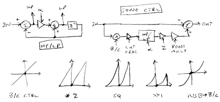
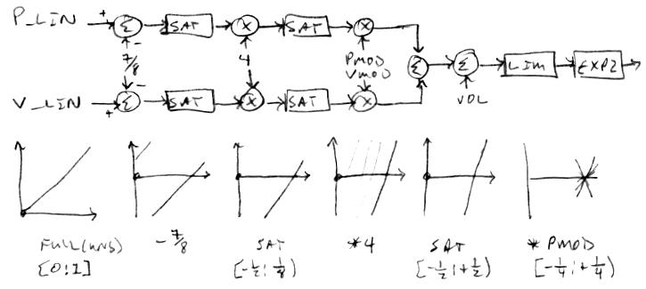
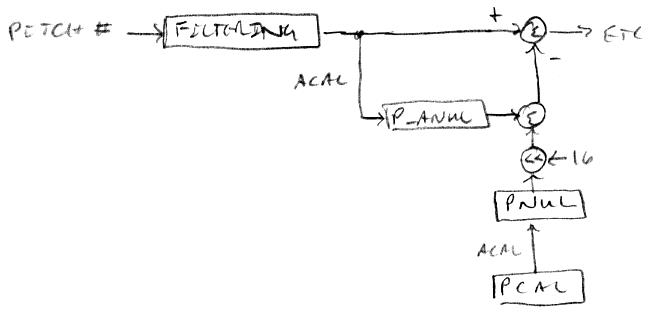
At the upper left is a HP (high-pass) and LP (low-pass) filter which we add / subtract from the input to form the tone control at the upper right.  At bottom is a method to linearize the boost/cut encoder.

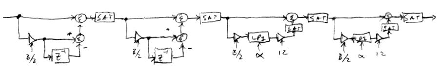
For the filters we use the standard first order type, with no delay on the low pass output (in order to make the larger construct feed-forward).  We employ a low pass filter for the bass control and a high pass filter for the treble control.  We cascade a bass and a treble unit to get both controls.

The transfer function of a first order low pass filter is:

out / in = alpha / (1 + z^-1(alpha - 1))

The transfer function of a first order high pass filter is:

out / in = (1 - z^-1) / (1 + z^-1(alpha - 1))

where alpha is:

  alpha = 1-e^(-2 * pi * Fc / Fs)

Conversely, if given alpha then the cutoff frequency is:

  Fc = -ln(1 - alpha) * Fs / pi

Boost / cut is accomplished by multiplying the filter input with the signed boost / cut control value, multiplying this by the cut fraction, selecting the boost / cut filter frequency, doing the filtering, multiplying the result by the boost multiplier (only if boosting), then summing the result with the input value - which is a surprisingly involved process!

It's not obvious, but you need to use separate filter frequencies for boost and cut.  For the bass control, the cut filter frequency should be approximately 2x the boost filter frequency.  For the treble control, the boost filter frequency should be approximately 2x the cut filter frequency. 

The cut fraction subtracted from one should roughly reflect the maximum cut ratio (e.g. 0.9 for -20dB).  The boost amplitude multiplier (multiplied by the cut fraction) should roughly reflect the maximum boost ratio (e.g. 10/0.9 = 11.1 for +20dB), though all things DSP tend to deviate, particularly at higher frequencies.

Since the filters are only first order, there is some interaction going on in the midrange.  A good question here is: what is the center of "midrange"?  My ears and brain tell me this is somewhere around 500Hz or so when listening to a variable tone source.  The geometric mean of 20Hz and 20kHz is 632Hz.  Another good question is: how much boost / cut is necessary?  +/- 15dB sounds sufficient to my ears, and this keeps midrange gain variation fairly reasonable.

To minimize overload, the control and cut fraction multiplications are placed before the filter where they form an attenuator.  Signed control here is usually in the range [-0.5:0.5) which knocks the amplitude down by at least 1/2, which, along with the application of the cut fraction, gives sufficient headroom for the high pass calculation inside the filter.  Obviously, the output of the filter output must then be multiplied by 2 to compensate.

Scaling of the boost / cut control is a critical element of the design.  Going from cut to boost involves an large gain differential (boost gain), which could be especially obvious around zero.  And the general spacing of the control detents is quite non-linear.  If we multiply the signed control value by 2 modulo to give dual unsigned ramps, square this, divide it by 2, and then translate the negative side ramp down by flipping the MSb, we end up with a construct that linearizes the control pretty well over the full range.

For various boost and cut values, the curves are not symmetric about the 0dB axis.  Fixing this involves scaling the cut mode cutoff frequency with some function of the cut strength.  I chose not to fix this, as first order filters are pretty indistinct sounding in the first place.  The ear really can't discern whether or not it's hearing scientifically accurate first order filter shelving. 

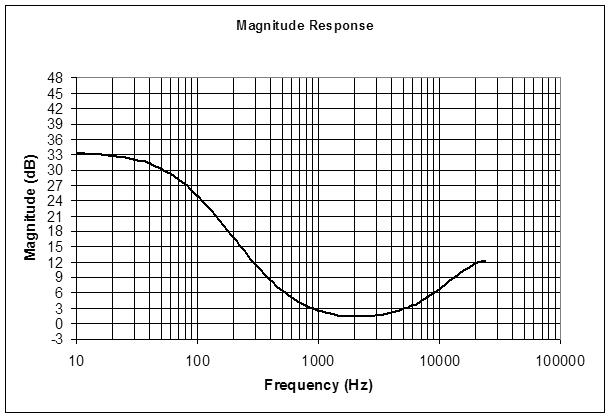
Anyway, here it is the simulation boosting the bass and treble by ~9dB:

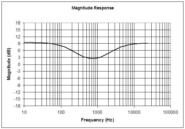
You can see some raising of the midrange here where the bass and treble boosting overlaps, with the center of the dip somewhere around 700Hz.

Implementing mathematically perfect (literally textbook - see Zolzer's treatment) bass and treble controls involves dynamically solving a LOG and a ratio of TANs (though the TANs could be pre-computed if not varying the cutoff frequency), which is way more trouble than the results are worth IMO.  If one were building a mixing console, or a multi-band equalizer, then the computational effort would be easier to justify.

Here's a sample of it in action: [MP3].  First the bass is cut then returned quickly to zero, then it is boosted and returned quickly to zero, then the same is done for the treble control.  The test signal is white noise, which I probably should have cut down on the high end some as it swamps the low end.

Posted: 5/15/2019 11:26:46 AM
dewster

From: Northern NJ, USA

Joined: 2/17/2012

Something In A Shade Of Grey

Noise filtering is interesting because it can change the character of the noise quite profoundly.  There is a state-variable filter following the noise generator, but it isn't parametric, so there's no direct way to scoop out the midrange.  Looking into the various noise types, there's white (equal amplitude), pink (equal energy per octave), and grey (equal loudness).  White sounds really "hissy" with a pronounced upper midrange - indeed, it directly reveals the Fletcher-Munson response of our ears.  Pink sounds more balanced, though somewhat muted.  Grey sounds like the roaring ocean, with more pronounced bass content and somewhat pronounced treble.  Anyway, I figured I could recycle some of the ill-fated loudness filter code, now that I understand tone controls better in general.

As usual, the design process begins with a spreadsheet: [LINK].  My grey noise filter is based on a cascade of first order shelving boost filters.  For the low end filters we use the standard first order type, with no delay on the low pass output (in order to make the larger construct feed-forward).  For the high end filters we employ a simple differentiator.  Because this is a boost filter (rather than a cut filter, like the loudness filter was) we sprinkle in a lot of saturation control after summations and multiplications which can produce values larger than 1:


Because it relies on the psycho-acoustics of the human ear, there is no single "correct" form of grey noise.  From the Wiki, one possible grey response is a broad dip centered around ~2kHz, with rounded second order slope on either side, which we are approximating here, and I believe this is similar to an inverted A weighting, but with a shelving on the both ends.  Other possible grey responses are the inverted ITU-R468, and the inverted Fletcher-Munson.  All of these boost the bass, and to a lesser extent the treble:

The transfer function of a first order differentiator is:

  out / in = 1 - z^-1

Boost is accomplished by multiplying the filter input with one half the control value (to provide filter headroom), doing the filtering, multiplying the result by the boost multiplier, then summing the result with the input value.  The boost multiplier should roughly reflect the maximum boost ratio (e.g. 10 for +20dB).  To minimize overload, the control multiplication is placed before the filter where it forms an attenuator.  The treble sections use lower overall gain so we place these first for overload purposes.

Since there are two stages of low pass and two stages of differentiation, this effectively gives a squared control knob response, and so no further scaling is needed in order to give a fairly linear (in dB) response curve.

After all this, it seems similar audible results can be obtained by turning up the global bass and treble controls I just added, so I'm not sure how long this filter will remain in the prototype code.  Sometimes you have to play with things for a while to realize their value (or lack thereof).  If nothing else, I'm more acquainted with grading filter responses in boost / cut scenarios.  A second order is actually often what you want when approximating a first order variable shelving response, and I may give this a go with the tone controls too, which are currently first order.

Here's a sample which gradually goes from white to grey, then quickly back to white: [MP3].

You must be logged in to post a reply. Please log in or register for a new account.