Let's Design and Build a (mostly) Digital Theremin!

Posted: 2/18/2021 11:20:05 PM
dewster

From: Northern NJ, USA

Joined: 2/17/2012

The New Adventures of Curve Pitch Correction

Roger and I have been discussing refinements to the D-Lev pitch correction, and these conversations have really helped me to better understand what it should and shouldn't be doing.  Experiments with some new ideas over the past couple of days have produced a design that I'm much happier with in terms of performance and basic functionality.  Some recent history:


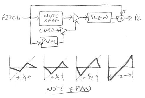
At top is a high level view of the previous pitch correction.  The pitch number comes in and is separated into individual notes, which are treated equally by the note span knob (see next).  The span amplitude is controlled by the corr knob, which itself is modulated downward by the pitch axis velocity (pvel).  The result is slowed down by controlling the linear slew rate, and this is mixed with the original input to obtain the corrected pitch number as output. 

Below that is a graphical representation of the lately linearized note span.  Setting the knob to 1/4 results in the left-most graph: here the center 1/4 of the note is fully corrected, and this has the side effect (literally!) of increasing the pitch slope in the 3/4 wide transition regions between adjacent notes.  Similarly, setting the knob to 1/2 gives 1/2 note width of correction, 3/4 gives 3/4 correction, and the knob set to full gives us full correction, or steppy quantization, where the notes "pop" from one to the next.  Keep in mind that these graphs are showing you what it takes to correct the pitch, not the final corrected pitch.

A main point that gets lost in these technical descriptions: once you've simply slowed the correction down - by slew limiting, or by 1st or higher order low pass filter, etc. - you could actually just stop there as you've accomplished 90% of what we think of as "full" pitch correction, with the remaining features nice to have but not entirely essential - and they can be quite fiddly to implement (look at me, I'm years into this).  You don't even need a variable span function because even a little delay will slant the steep edges of steppy quantization, rendering them inaudible.  You do need the action of the corr knob though, as this "humanizes" the perfect correction by letting some pitch error back in.  Perfect pitch correction is audible with male voice presets, as the rich harmonics interacting with the resonance peaks give the ear a lot of relative pitch cues - remove all pitch variation and it sounds like a car horn.  Indeed, many vocal simulators introduce a small random pitch variation to combat this.

For the longest time I thought higher order filters were the way to go here as they impart polynomial-like curves to the transitions.  But, just as the shortest distance between two points is a line, linear slewing is the quickest way to transition from off-pitch to on-pitch, and the ear isn't all that sensitive to the shape of the correction.  Slowing is actually easier to implement via low pass filter because it functions ratiometrically, so the rate of change is simply set by the cutoff frequency; whereas slew factor is directly proportional to accumulator width, therefore absolute slew rate can be affected by where you place attenuation in the signal path, and in that sense linear slew rate limiting is ironically non-linear.  Who would think that exponential decay would be linear?  I digress...

Here's the design as of today:


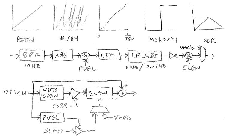
At bottom you can see that the main topological change is that the pitch velocity is now downwardly modulating the slew rate instead of corr, and this rate can be overridden by vmod.  I should have drawn the slew|vmod mux in the top diagram as well because it isn't new, though the operation is slightly different.  The purpose of the mux is to speed up the slew at very low (generally sub-audible, the location in the volume field can set via the vloc knob) volumes to center up the next note so it comes in on-pitch.  The mux comes after any pvel modulation, so it overrides that.  I actually tried pretty hard to come up with an arrangement that didn't override pvel, but came up empty.  The pvel modulation of slew decreases the slew rate (increases the slew time) when the right hand moves, which helps to mask any steep edges on the correction signal via increased filtering.

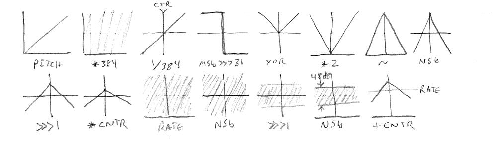
The main problem with conventional velocity detection as applied to pitch correction is that it either has too little gain and doesn't kick in fast / often enough to lower the filter frequency - you hear stepping when span is high, slew is low, and you move your pitch hand too slowly to a neighboring note - or it has too much gain and effectively turns off pitch correction for any pitch hand movement at all.  Pvel still has a use though, because it can enable lower slew settings.  Seen above is a method I'm using to increase the general usefulness of pvel.  Graphically the pitch number is modulo multiplied by the number of notes/octave * octaves (12 * 32) in the linear pitch range, giving us 384 full scale ramps.  Looking at a single ramp, we XOR it with its full width sign bit, which gives us a half height triangle for each note.  This large scale ramping gains up the velocity detector to movement, and the cyclic nature and low harmonic content give it something significant to "chew on". Just moving the pitch hand from note to note will create signifcant change, and sweeping it through the field will generate a low frequency, high amplitude signal.  Anyway, this is fed to the velocity detector shown below the graphs.  A bandpass filter removes DC & noise, and gains down all but low frequency changes.  Then the absolute value is taken, and this is multiplied by pvel and limited to give a large saturation zone.  This is fed to a first order bi-modal low pass filter, which has a cutoff frequency of 10Hz for inputs larger than the output, and 0.25Hz otherwise, creating a kind of doubly leaky peak hold which reacts quickly.  Finally a bit inverse changes the direction, and this is used to modulate slew.

I like to include a "berserker" setting to any controls whenever possible.  Maximum span gives a very edgy and snappy quantization, minimum none; maximum corr gives 100% correction, minimum none; maximum pvel effectively turns off correction for all but the tiniest of pitch hand movements, minimum off; maximum slew gives over 5 seconds of slew time, minimum 21 ms; and vloc positions vmod over a -96dB to 0dB range.  Crazy settings tend to reveal the thing functioning and create audible artifacting.  So any real use of this module for unobtrusive pitch correction will necessarily employ the more moderate ranges of at least some of these controls.  I tend to use a lot of correction, and my settings are:

slew=16 (1/2)
pvel=16 (1/2)
span=31 (max)
corr=31 (max)
vloc=18 (vmod transition @ -42dB)

Max corr is getting a little fatiguing sounding but I can't bring myself to lower it.  Sometimes I up the slew a little for really slow songs, though now I may be able to rely on the improved pvel.  One could use even lower slew with higher pvel, but for really low slew some backing off of span is required to reduce low velocity discontinuities, and I think slew should be used as the go-to knob for the overall correcting effect, with the other knobs used as seasoning.

Posted: 2/21/2021 9:10:21 PM
dewster

From: Northern NJ, USA

Joined: 2/17/2012

Forget Paris Pitch Velocity

Ha!  Finally what seems like a real, solid breakthrough with pitch correction!  Using pitch velocity to slow the error slew rate is a dead end.  As I stated earlier, the main problem with it is at the note transitions: play too slowly and you get a full slew rate note step, so you either need the velocity gain turned way up - at which point it's pretty much strangling all correction at the slightest move, and then what's the point?  Or you need slower slew as a base, and then what's the point?  Well, the main point in the second scenario is that it allows you to use somewhat faster base slew, but pitch velocity is just a sort of vague helper there and I'm not sure it's worth all the effort.  It also kind of weirdly modulates, and I've improved that quite a bit I think, but it's still too erratic to rely on alone.

This morning I hit on the idea of using the position in the note as a direct slew rate modulator.  At first I tried slowing the slew rate at the note boundaries, but that was kind of difficult to set with the knobs.  Then I instead tried speeding up the slew rate towards the center of the note, which allows the "slew" knob to set the minimum or slowest slew rate, and the newly named "cntr" knob to control the "magnetic" feeling at the center of the note.  I followed this with a bimodal lowpass filter with 2Hz/10Hz rise/fall, which keeps note sweeps from falling into the "fast funnels" at the note centers, and also softens the switch to full quantization.  I don't like having more than the one time constant (the slew rate) but if they're fast enough they're not too noticeable.

I need to play with it and perhaps tinker with the arrangement, knob scaling, and funnel shape, but even now in its rough state it feels like a genuinely positive addition to the pitch correction module.  Almost no "magic numbers" in the code, which usually indicates good design.

Posted: 2/23/2021 3:33:43 AM
dewster

From: Northern NJ, USA

Joined: 2/17/2012

Slew Rate Modulation

Been puzzling over how to scale the pitch correction slew and cntr knobs, and finally hit on the following in the linear domain:


As usual the pitch is modulo multiplied to get single notes full scale.  This is XORed with the MSb of the result shifted full scale, multiplied by 2, shifted down 1/2 to make it signed by flipping the MSb, shifted right once to divide by 2, and multiplied by the cntr knob value.  The slew knob is bit inverted (not shown) to give us the rate, which reverses the sense (I briefly toyed with not inverting it, but it feels better to have quantization when slew=0).  It is shifted down 1/2 to make it signed, divided by 2, then shifted back up.  This is then added to the result of the previous cntr operations just described.  Not shown: this linear result is bi-modally low pass filtered, then brought into the exponential domain by flipping the MSb to add 1/2 full scale, adding 1/2, then passing it to the unsigned integer EXP2 library function.

This process gives us a slew knob that covers 48dB, or 8 bits of range - you need at least 48dB or so of slew adjustment to go from hard quantization to snail slow transition.  The cntr knob tilts the lead-in and lead-out, using slew as the pivot point, with the result that both knobs are able to cover a total of 98dB, or 16 bits.  The whole reason we're doing this is to produce an average slew rate regardless of the setting of the cntr knob, which pretty much eliminates any sense of interaction between them.  Though the low pass filter favors falling over rising by a 10:1 ratio, so there is a dynamic which tends to slow the average slew down.  I'm still experimenting with the settings of the low pass filter, but 1Hz & 10Hz seem to be working well.

Here's a demonstration recording I just made using slew=20, cntr=16:  [MP3]

The notes are played staccato for the first half, and the male voice being perfectly corrected sounds rather like a car horn / reed organ.  Without changing any settings the second half is played much more dynamically with a little slower tempo, and I think you'll agree that the pitch corrector is able to handle these two very disparate playing styles quite well with no adjustment.  Increasing cntr actually helps to smooth the note transitions, while accentuating the note centers.  I also set vloc=18, which snaps the pitch to the note centers when the volume is subsonic - this assists the starting of notes on-pitch.

[EDIT] I must say, I feel kinda bad for analog Theremin designers because they can't just drop into linear space, where thinking about and implementing this sort of scaling is quite simple and direct, and then return to exponential space via a non-polynomial (only 6% error max for larger inputs) EXP2, which only consumes 7 cycles. 

At the time when I was writing my integer and floating math libraries, I wondered if I'd ever recoup the copious time and effort invested.  It was an incredibly entertaining, engrossing, and enlightening activity, and just for that alone I'm quite happy I undertook the months-long project.  But it really prepared me for the unforeseen mountain of knob scaling that had to be climbed later.  It taught me a lot about bit twiddling and other assembly level efficiencies too - conventional maths alone won't net you the smallest / fastest code.  If you ever find yourself designing a processor and assembly language, do a math library as your first coding project.  It will immediately give you feedback as to the relative value of your opcodes (an impossible thing to know 100% up-front) and it will teach you a lot about modulo math.

Posted: 2/23/2021 6:36:58 PM
pitts8rh

From: Minnesota USA

Joined: 11/27/2015

I played with the correction this morning and I was getting some very good results.  It sometimes feels like instead of pulling you in to the nearest note (sometimes against your will and to the wrong note) it is just broadening the correct pitches in space, making them easier to land on.  I don't even have anything optimized and there are very few artifacts, and when assisted by unquantized pitch preview as a reference I don't think I hear any (won't know until I record and play back).

I always get disturbed when features don't have enough knobs, but so far this seems to be distilled down to a pretty effective and user-friendly format. Very nice!

Posted: 2/24/2021 1:59:24 PM
dewster

From: Northern NJ, USA

Joined: 2/17/2012

"It sometimes feels like instead of pulling you in to the nearest note (sometimes against your will and to the wrong note) it is just broadening the correct pitches in space, making them easier to land on."  - pitts8rh

1. Slowing down error correction at the note boundaries tilts the pitch steps flatter, but even a little slowing will do that sufficiently.  Much more importantly it increases the range of variability / expressiveness of half step portamento timing because the boundary correction isn't as dominated / driven by what once was a constant slew rate, pulling you this way and that like a lassie.  Likewise, accidentally positioning to just before / past the edge of the note you intended to land on doesn't instantly start dragging you quickly away in the wrong direction; you are instead given some time to react to and therefore correct the situation more gracefully.

2. Speeding up error correction at the note centers emphasizes them, but this creates potholes that wider range portamento (legato?) playing will fall into due to the increased relative dwell time there.  The bi-modal lowpass filter paves over these potholes as the portamento rate increases.

In this second respect it's rather like the velocity sensing approach used previously, but velocity sensing often aggravated note boundaries.  The introduction of two additional time constants isn't my preference but it seems warranted, and the velocity approach required them too, as well as other fiddly complexity (gain curve, saturation, windup / headroom, etc.) which made it ugly and a subjective tradeoff bear to work on.  I very much like the fact that this new approach is unified, and not two separate mechanisms which may at times work against each other.

I think it's even easier now to turn correction way up and not hear it too much when playing dynamically - which is probably a danger, at least from an ear fatigue standpoint.  Backing off on the "levl" knob for presets with prominent formants (strings, humans, etc.) seems to help a lot.  I don't think I'll ever adjust "span" down from its max (31) but never say never I guess, and other players may find it somehow useful for their playing styles.

Posted: 3/1/2021 10:54:23 AM
dewster

From: Northern NJ, USA

Joined: 2/17/2012

Hard and Fast Limits

Roger suggested an encoder behavior feature that he'd seen in some other hardware that he really liked.  Say you are at or near one end of a knob's limits and want to go to the other end.  Even with velocity this can take two or more quick spins for those parameters with a lot of states (e.g. filter cutoff has 8*2*12+1 = 193 states).  Those spins can be hard on the encoder, shortening its lifetime, and they can be somewhat tedious to perform.  Hard stops at the limits are useful for navigation purposes, because rapid spins go from end to end without jumping over the fence.  If, say, the user interface screen selector were instead modulo - no limits, just flip min / max when the limit is reached - then the user would need to have in mind the order of the screens to know where they were, and which way to go to get where they wanted to be, and couldn't rely on certain important screens located at or near the nonexistent limits - too much thinking required!  Clearly limits have costs and benefits - can we somehow get the best of both worlds?

The answer is yes, and the key is to look at the derivative of the position, or velocity.  If you approach a min/max limit with any velocity it should just stick at the limit.  If you approach it more slowly then it should go through the limit to the other side.  After some analysis I discovered that most of the basic functionality to implement this was already there in the software.  Velocity is a linear one second maximum (from full scale) decay of summed knob detent events, but the decay will go to zero in less time than this when spinning the knob more slowly.  So when a spin hits a limit we look at the velocity before the last detent happened (something the software has to know in order to implement velocity in the first place) and if it is zero we go through the limit to the other side.

A while back I'd implemented another of Roger's encoder behavior suggestions, which was the zeroing out of the parameter when the knob was pressed.  This also is a really great feature, with it you can quickly and easily zero out an entire page with seven presses, completely disabling some function.  So hat tip to Roger for these excellent UI (and other) ideas, keep 'em comin'!

Posted: 3/3/2021 8:50:57 PM
dewster

From: Northern NJ, USA

Joined: 2/17/2012

LCD Backlight Dimmer

There is a brightness control knob for the LED tuner, but the LCD backlight has been blaring away unbridled, so high time to implement a dimmer for that too, but for something pretty simple seeming it took a while to get it all straight.


The method is shown above.  A processor register is incremented at the interrupt rate of 48kHz, with the increment value sized to make the ramping up sum roll over at 300Hz.  I picked this frequency because the hum filters configured for either 50Hz or 60Hz have a common notch here.  Since the eye response to brightness is logarithmic we need a roughly exponential function somewhere to perceptually linearize the knob setting.  I started out by squaring the Bklt knob value, but ran into resolution issues, and the solution was to instead square the ramp.  This is offset by the Bklt knob value, and the overflow bit is routed to a GPIO bit, which is used to drive a transistor.  If you think about it, the counter will overflow more often the larger the offset is, and this is first order modulation. 

The transistor driver has a low pass filter on the base which smooths out the pulse width modulation (and hopefully any interference with the axes) and the drive current is sensed and limited by the 50 ohm resistor to ground.  The 22k resistor provides some feedback which helps to moderate the transistor full on and off points.  We're driving the backlight LED from the +5V supply in order to relieve the FPGA demo board 3.3V regulator, which doesn't have the best thermal management.

Posted: 3/4/2021 4:35:35 PM
dewster

From: Northern NJ, USA

Joined: 2/17/2012

Second SPDIF DAC Box

Bought a second DAC box off Amazon back in October for $10 USD:

https://www.amazon.com/Digital-Converter-Tackston-Optical-Toslink/dp/B086SC4C1L

Works fine, L&R may be swapped IIRC, haven't tried the headphone out or the SPDIF in.  Thought I'd open it up today and check out the guts:

Advanced Monolithic 3.3V LDO regulator, unmarked op-amp, NS6000 main IC that I can't find any specs for - I can't even identify the logo:

https://how-to.fandom.com/wiki/How_to_identify_integrated_circuit_(chip)_manufacturers_by_their_logos/A-E

Posted: 3/4/2021 8:50:02 PM
pitts8rh

From: Minnesota USA

Joined: 11/27/2015

That's how my latest look as well.  I bought a batch from ebay, I think from the same source I used last time, and was surprised when I popped one of these open to gut it for the D-Lev audio board. The previous ones had absolutely no components on top except for connectors, and I believe it was actually a single-sided pcb.  Under the microscope the traces on the older boards looked really bad.

I had already stacked one of the old ones on the new D-Lev audio board but when I saw this I had to remove it so I could put two of the same type on (purely for OCD).

These look much better in many ways.The outline is a little larger than the old one and the vias are much tighter for pushing header pins through for stacking. But thankfully they still work.  Wicking up that ROHS solder is a chore though.

I looked around quite a bit for just the board alone without the box, but the only ones I find are twice the price and they still have connectors to remove.

As I mentioned in one of my emails, mine have a 50 ohm input impedance.  The previous ones were 75.  Not ideal when using a resistive divider for a 75ohm source impedance. 

Posted: 3/5/2021 12:09:34 PM
dewster

From: Northern NJ, USA

Joined: 2/17/2012

"I bought a batch from ebay..." - pitts8rh

How much did you pay a pop?

"I had already stacked one of the old ones on the new D-Lev audio board but when I saw this I had to remove it so I could put two of the same type on (purely for OCD)."

I don't think that's OCD, that's good sense!  My early headroom experiments with the first box showed asymmetric analog clipping significantly before digital clipping, which is wrong IMO, but maybe they were going after a particular analog gain (don't know why though, line level is all over the place) and damn the secondary clipping.  I wonder what this new one does.

"As I mentioned in one of my emails, mine have a 50 ohm input impedance.  The previous ones were 75.  Not ideal when using a resistive divider for a 75ohm source impedance."

Yes, R4 measures 50 ohms to ground.  75 ohms might make more sense as RCA coax tends to be around there (or so I have read) and 50 ohms strikes me as pretty stiff to drive.  The switching rate is a little over 6MHz, so not too onerous in terms of signal integrity.

The SPDIF standard calls for 75 ohms and 0.5Vpp open circuit.  With 3.3V drive I'd pick 500 ohms series, maybe 100 ohms to ground (88 is the calculated value for 75 ohms, beef up the voltage a bit for the 50 resistor in the SPDIF box?).  Series C from FPGA pin to divider > 1nF, maybe 10nF or 0.01uF.  I would bet that the IC input has a ton of margin.

You must be logged in to post a reply. Please log in or register for a new account.