


dewster, you kind of beat me to it.
I was going to ask in the Moog Melodia thread if anyone had actually built one from those circuit diagrams.
Have to admit to having looked at the plans and thought that it might well be worth giving it a go...but then nothing is ever so simple...like the coils and caps...and probably discontinued components...
But apart from all of that, how doable would such a project be?
Goals for a TW Theremin
Posted: 10/27/2014 9:27:36 PM
Posted: 10/27/2014 10:32:27 PM

"But apart from all of that, how doable would such a project be?" - RoyP
Abstractly, we're building oscillators with stability on the order of a ham VCO, but with higher voltage swing, narrower tuning, and laxer spectral purity. It would be nice to do this with common components and single winding non-variable coils (RF chokes). There are single FET and single CMOS inverter oscillators that I know of that can do this, but tuning is the issue. There could be coarse tuning on the PWB with fine tuning on the front panel, or a multi-turn pot on the front panel to handle the whole range (assuming resistive tuning of some sort). Varying the transistor bias might give one enough range for fine tuning? This is a bit out of my league, though I'm game to try stuff out on the bench. Tuning methods that vary the internal oscillator feedback delay are probably out as they don't optimize voltage swing, methods that change the inductance via saturation probably require too much power, so this leaves changing the capacitance somehow.
Perhaps capacitive padding to get close and antenna length adjustment for fine adjustment would be sufficient? This too is outside of my experience. I kind of wonder why the Melodia doesn't use small fixed capacitors in series with larger variable capacitors for the tuning. Since spectral purity isn't an overriding issue, I wonder if diode conduction could be somehow used, ala the poor man's LPF from PAIA?
[EDIT] Just checked my "rod" Theremin design spreadsheet, a change in length of 10mm diameter antenna from 400mm to 410mm gives a change in capacitance of +0.12pF or +1.7%. This could likely work for fine tuning, but probably doesn't have enough range to cover the ground necessary for coarse tuning. Requiring builders to buy specific telescoping antennas is probably as bad as requiring them to buy specific coils.
Posted: 10/28/2014 1:57:15 AM

From: Eastleigh, Hampshire, U.K. ................................... Fred Mundell. ................................... Electronics Engineer. (Primarily Analogue) .. CV Synths 1974-1980 .. Theremin developer 2007 to present .. soon to be Developing / Trading as WaveCrafter.com . ...................................
Joined: 12/7/2007
"Just checked my "rod" Theremin design spreadsheet, a change in length of 10mm diameter antenna from 400mm to 410mm gives a change in capacitance of +0.12pF or +1.7%. This could likely work for fine tuning, but probably doesn't have enough range to cover the ground necessary for coarse tuning. Requiring builders to buy specific telescoping antennas is probably as bad as requiring them to buy specific coils." - Dewster
I hate to keep plugging it -
But my screw adjustable antenna was able to more than cope with required tuning under extreme environmental / external capacitance change. Forget telescopics, one can get course tuning with those, but thats it.. The screw antenna gives fine adjustment of length 0ver whatever size one constructs (30cm to 50cm retains 10cm "grip" - as in 30cm screw, 30cm tube).
"I kind of wonder why the Melodia doesn't use small fixed capacitors in series with larger variable capacitors for the tuning. "
because if you do this, the usable tuning area packs into a small part of the variable capacitors rotation.. Any series capacitance less than the maximum value of the variable and I have found it becomes noticeably non-linear - to get low capacitances using cheap variable capacitors (usually >> 50pF) the non-linearity becomes unusable .
Just dug up past .xls: (this was using a cheap am variable C)

There is another screw adjustable method thats not quite so good, but is fine for tuning a loop... Have an adjustable "ground antenna" near to the sensing "antenna" - For the loop, this can be a horizontal adjustable 'stick' in front of the loop.
But for simple adjustable "loop" dont use a loop - use a horizontal adjustable stick.
(I suspect that if using a Melodia style volume sensing plate inside the chassis, you could probably construct this with FR4 and actually build a tuning capacitor into the plate using PCB (FR4) as the dielectric and the moving plate.. Spindle, spring, and hole to knob on the outside.. Probably be as good as these cheap AM polyester tuning caps. But you can buy 1pF to 15pF good quality tuning caps for between $10 and $20 each from surplus RF suppliers)
Anyway - Thats enough from me ;-)
I am NOT getting involved in this thread! - I am only interested in beating up new members and getting into fights!
;-)
(apart from which, I have decided to go it alone - been here before..)
Fred
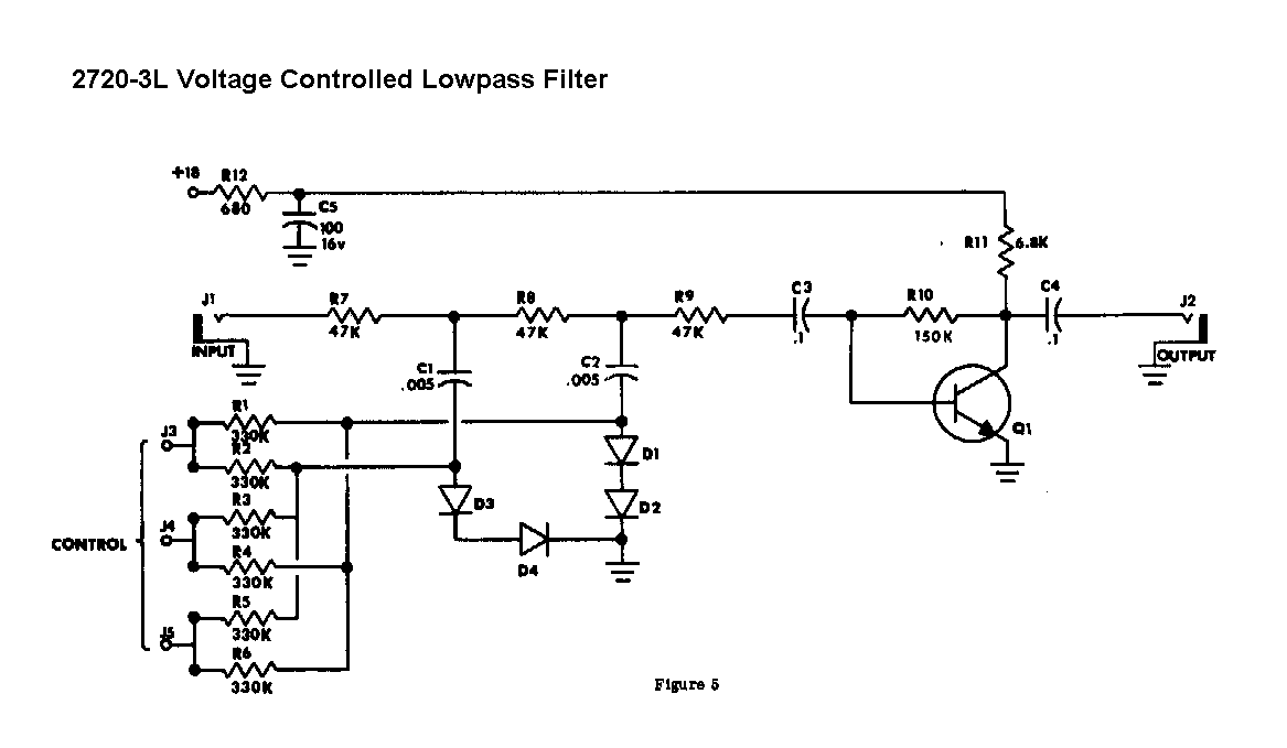
(and that PAiA LPF! Ugh! - Nah, if you want to be cheap, thats ok - but theres no reason to be nasty! ;-)
Also, note that with the Melodia, the variable capacitors are on the "antennas" where voltages are high - this is the best place for them as tuning here keeps the linearity (unlike tuning the reference oscillator as per the EW). It is a real pain to do any kind of electronic tuning at this point - not primarily because of "spectral purity" but because of thermal drift.
BTW - I calculate the inductance of the Melodia tank at about 290uH .. You can get 226uH -> 499uH between pins 1+2 of a 42IF106 IFT, so it should cover the required inductance (perhaps a slight reduction of tank capacitance to about 3n3 ?)- The AL of this part is adjustable from about 20 to 47, turns 1-2 = 103, 2-3 = 50, 4-6 = 27. Resistance 1-2 = 3.2, 2-3 =1.6, 4-6 = 0.1
These parts are cheap and easy to get from Mouser.
Posted: 10/28/2014 4:03:31 AM
"I hate to keep plugging it -" - FredM
Actually I was hoping you might step in and talk about it, it being your excellent idea and all!
"because if you do this, the usable tuning area packs into a small part of the variable capacitors rotation.. Any series capacitance less than the maximum value of the variable and I have found it becomes unusably non-linear."
Yeah, I was thinking along those lines after I posted.
"I suspect that if using a Melodia style volume sensing plate inside the chassis, you could probably construct this with FR4 and actually build a tuning capacitor into the plate using PCB (FR4) as the dielectric and the moving plate.. Spindle, spring, and hole to knob on the outside.. Probably be as good as these cheap AM polyester tuning caps."
Interesting.
"But you can buy 1pF to 15pF good quality tuning caps for between $10 and $20 each from surplus RF suppliers"
That goes into the specialty component area I'd like to avoid.
"Also, note that with the Melodia, the variable capacitors are on the "antennas" where voltages are high - this is the best place for them as tuning here keeps the linearity (unlike tuning the reference oscillator as per the EW). It is a real pain to do any kind of electronic tuning at this point - not primarily because of "spectral purity" but because of thermal drift."
With the FET Clapp or Colpitts, maybe do the tuning across the larger capacitors that the FET uses as feedback / drive? That point is rather low voltage. I need to play around with this some to see what is possible.
"BTW - I calculate the inductance of the Melodia tank at about 290uH .. You can get 226uH -> 499uH between pins 1+2 of a 42IF106 IFT, so it should cover the required inductance (perhaps a slight reduction of tank capacitance to about 3n3 ?)- The AL of this part is adjustable from about 20 to 47, turns 1-2 = 103, 2-3 = 50, 4-6 = 27. Resistance 1-2 = 3.2, 2-3 =1.6, 4-6 = 0.1
These parts are cheap and easy to get from Mouser."
Do you know the self capacitance of the 42IF106? If I wanted to go series resonant that would require large inductance with low capacitance. I want to avoid the parallel tank + series EQ = Moog approach.
"... this is a hugely improved version of the circuit I emailed you.."
That board is looking good Fred!
Posted: 10/28/2014 6:27:21 AM
From: Eastleigh, Hampshire, U.K. ................................... Fred Mundell. ................................... Electronics Engineer. (Primarily Analogue) .. CV Synths 1974-1980 .. Theremin developer 2007 to present .. soon to be Developing / Trading as WaveCrafter.com . ...................................
Joined: 12/7/2007
Hello Dewster -
No, I dont ;-) .. I just hit a block on that a couple of days ago - Thought I understood it, but then...
Heres a brief update on my oscillator - With what you have before, you should see what ive done. (clue - the bottom switch is the inverter driving the other switches, which are simply acting as a buffer.. There is a delay controlled by the CV.. This varies the frequency. The bummer is the diode temperature dependence, but I have a way to overcome that as you have seen... Sine output is also available (not shown). A few other components (not shown) are required for decoupling and isolating / buffering the sine output. The circuit operates happily with a supply from 3V to 5V or a standard 4053 can be used for lower frequencies at up to 16V, but some resistor values need to be changed and a limiting resistor placed in series with the inductor (much better to stay at or below 5V - I have actually fitted a separate 78L05 regulator to each oscillator on the board)
This is not buildable in the form shown - IC pin / track capacitances actually determine the performance and a resistor value must be set based on this - but the oscillator always starts - it cannot fail.. Antenna voltage however is dependent on correct component values (can be 180V P-P if correctly 'tuned'). I use a 42IF106 wired as ~1mH, and "tank" capacitor to suite required frequency / sensitivity (~100pF) and get about 15kHz adjustment at ~500kHz with the CV from 0V to 5V.

Equivalent to:

("Delay" is more a voltage controlled phase shift than "delay" and delays the rising edge from the "inverter" only.) .. As you can see, this is a variant of Dewster's series CMOS oscillator he proposed way back in the digital theremin thread.. Without that I would never have come up with this - and without his gentle correction of my stupid thinking with regard to LC oscillator operation, I would still be thinking I understood them when I didnt! ;-)
Anyway - I have already said too much on this thread. I need to back off and let TW go its way. I realize that I am way too loud here - apart from which I really dont have the time. Good luck with the project!
Fred.
Posted: 10/28/2014 10:57:03 PM
Fred, I wouldn't have thought of using CMOS switches for Theremin oscillator duty, but the analog connection certainly opens up possibilities! It looks like you've had a fair amount of experience with layout, which must really help with projects like this. Where I worked they used Mentor Graphics on Unix workstations, which had such a cobbled together / shaky feeling I never wanted to get near it.
=============
Re. the 42IF106: from your previous posts it seems capable of reaching 1.4mH, which might provide enough adjustment if placed in series with a larger fixed RF choke. Then maybe do fine tuning with your threaded antenna idea.
=============
One thing that's been in the back of my head is using an NPN in lieu of a FET in the Theremin adapted Clapp oscillator. So while I should have been simulating the Moog electrically variable capacitor, that time was instead spent simulating and benching an NPN Clapp:
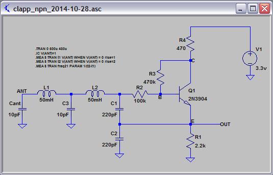
It oscillates around 130kHz (chokes I had laying around) with healthy measured antenna swing of over 80Vp-p, doesn't stall, and the output at the emitter is a complex wave at a lowish impedance. No idea of stability over temperature. No idea yet where the operating point should be, but maybe rather low to keep sensitivity low and playability high. No idea of linearity once heterodyned. No idea if ESD might be more of an issue with bipolar vs FET.
[EDIT] Spice file here:
http://www.mediafire.com/download/tadw2invos42ooh/clapp_npn_2014-10-28.asc
Posted: 10/28/2014 11:31:47 PM
From: Eastleigh, Hampshire, U.K. ................................... Fred Mundell. ................................... Electronics Engineer. (Primarily Analogue) .. CV Synths 1974-1980 .. Theremin developer 2007 to present .. soon to be Developing / Trading as WaveCrafter.com . ...................................
Joined: 12/7/2007
Hi Dewster,
That Clapp looks good - For direct analogue heterodyning the waveform on the emitter is important.. "complex" can be great, but it can also be horrible ;-)
As for ESD - I suspect the the bipolar will be more immune simply because R2 is larger than on a FET and theres low z on the base - but you will be having a discharge device on the antenna, so its moot - certainly from a construction perspective FETs are more risky.
42IF106 with all windings in series can go 698uH to 1.5mH .. I am inclined to thinking you may need to reduce L1 L2 a bit and up the frequency a tad to guarantee that the tuning will be adjustable over required range (whatever that is) to compensate for tolerances of L1 / L2.
But at this time I dont actually have much clue about your thinking.. Mine is on analogue lines, but you may have other plans (?) .. I suspect you are thinking offset heterodyning or something of the like.
Been looking at the HC4046 a lot recently - wanting to perhaps substitute some of my LC oscillators for simpler PLLs (thinking of just having the LC's for the antennas) their problem is the delta/T on their VCO's (0.15%/K) but if a suitable correction voltage could be applied from a temperature sensor, they would be beautiful.. But at the moment the only way to use them would be to oven them precisely. I wondered how they were ever used in Demod applications, but then realized that DC drift doesn't bother these as the output is generally AC coupled..
And theres this nagging voice in the back of my brain saying "its a load of crap! Use a Clapp!" ;-)
Fred.
Re PCB layout - I am dreadful at it! All sots of rules like "no right angles" get broken because im lazy, and they dont seem to make any difference below about 1GHz! I use way thicker traces than I "should" simply because if I dont they get etched away when I DIY my boards ;-). The only thing I get more "right" than most hobbyists is in keeping signals "partitioned" sensibly (not running HF square waves parallel to audio tracks, that sort of thing) and ensuring good supply distribution and decoupling.. I am also aware of capacitive coupling to ground / supplies, so take care on sensitive traces.. But I never do any fancy deliberate 'capacitor' or 'inductor' constructions using tracks.. Its all basic common sense with some value tweeking if needed when the board capacitances are known.
Mentor? Ugh! .. I dont like the big names / industry standard packages at all.. Cadstar, Cadenza, Pspice, even EWB are a pain (IMO) but you gotta use them as most of the industry does.. The first EDA I bought was Spice-Age/ Spycycle back in the early days, and it was brilliant! - The Developer is a brilliant engineer who I contracted once on a large project for electrical / mechanical simulation of a wheel chair. Then there were a few packages which started good but weren't supported. I use Proteus and its fine for what I need for PCB, and is the only package I have that I can do everything (schematic, simulation, PCB) on .. The package I used before could have been great - it did the lot, and gave analysis of couplings on the PCB with fancy colored graphs showing signal densities and radiations etc, but it was too buggy and never got updated - LT-Spice is great for simulation, but I dont like Eagle and thats the only PCB editor it interfaces to (with difficulty).
Posted: 10/29/2014 12:13:52 AM
"That Clapp looks good - For direct analogue heterodyning the waveform on the emitter is important.. "complex" can be great, but it can also be horrible ;-)" - FredM
Just added the Spice file to that post, the waveform I'm seeing on the scope is quite similar to what Spice shows. Rounded on the top, kind of a first premolar jaggy shape on the bottom. The top flattens out if you grasp the antenna.
"But at this time I dont actually have much clue about your thinking.. Mine is on analogue lines, but you may have other plans (?) .. I suspect you are thinking offset heterodyning or something of the like."
One could use the oscillator for either digital or analog, but at the moment (because I'm a glutton for punishment) I'm thinking analog, which is why the frequency is so low. It's my supposition that high oscillator sensitivity at a low frequency will give low to moderate heterodyned sensitivity (for playability) when adjusted for best linearity. Just spent a couple hours at DigiKey pawing over cap trimmers (range, tempco, voltage, price(!), availability) and now need a martini.
"...their problem is the delta/T on their VCO's (0.15%/K)"
Generally hidden from the user in a feedback loop, the minute you try to use it you find out how non-linear and temperature dependent the elements of something in a negative feedback loop are allowed to get. (Just finished Self's power amplifier design book, a classic example of this. Self is freakily awesome in his thoroughness and, yes I'll say it, EE humor!)
"Mentor? Ugh! .. I dont like the big names / industry standard packages at all.. Cadstar, Cadenza, Pspice, even EWB are a pain (IMO) but you gotta use them as most of the industry does."
Industry are a bunch of killjoys when it comes to toolsets.
Posted: 10/29/2014 1:27:37 AM
From: Eastleigh, Hampshire, U.K. ................................... Fred Mundell. ................................... Electronics Engineer. (Primarily Analogue) .. CV Synths 1974-1980 .. Theremin developer 2007 to present .. soon to be Developing / Trading as WaveCrafter.com . ...................................
Joined: 12/7/2007
That oscillator runs beautifully! I suspect the emitter waveforms into a multiplier (not a diode mixer) will sound great.
I am trying hard to stop myself from taking any kind of "role" here ;-) .. But if you are going analogue, then I think you might want higher frequency and padding with an antenna capacitor to reduce sensitivity.. This just is from my experience, and could be missing by miles as I dont have any 'reasons' that explain it really - but it seems to me that "uncorrected" low frequency oscillators end up giving worse linearity than "uncorrected" higher frequency oscillators..
But I dont think your Clapp will do well with the kind of Ls and Cs required to raise the frequency and 'pad' the antenna in this way - the antenna voltage kind of depends (?) on big L into small C - which is how you get away with such minuscule currents.
Not sure how you plan to "adjust for best linearity" - Without any "active" correction, the only mechanisms I can see as possible are series capacitance to antenna for minor near-field improvement, and oscillator coupling for far-field improvement... Or an antenna curved towards the player! ;-) .. A 45 degree angled 1 meter length antenna with its base at the shoulder height of the thereminist will probably do the job! ;-)
But as I say, I dont know why there seems to be improvement for linearity (but never good linearity) for simpler designs when the frequency is higher .. The SC/Jaycars for example have better linearity than they should have AFAICS, and better linearity than I have got from anything running below about 400kHz without equalizing of some kind... But the TVoX does it, so its not impossible!
Too much for me though ;-) Give me a nice complicated closed loop active correction scheme any day!
Fred.
Oh, BTW - Both inductors are essential on that Clapp?
You must be logged in to post a reply. Please log in or register for a new account.