Antannae non-linear relationship

Posted: 10/23/2012 7:46:47 PM
RoyP

From: Scotland

Joined: 9/27/2012

Hello all,

I'm not sure if this is in the right forum but I'm going to go with it.

Basically, the question is what causes the non-linearisation in the theremin antennae?

This has probably been asked many times before but I can't find the answer thread.

Thanks.


Roy

Posted: 10/23/2012 8:29:51 PM
FredM

From: Eastleigh, Hampshire, U.K. ................................... Fred Mundell. ................................... Electronics Engineer. (Primarily Analogue) .. CV Synths 1974-1980 .. Theremin developer 2007 to present .. soon to be Developing / Trading as WaveCrafter.com . ...................................

Joined: 12/7/2007

Hi Roy,

Im not exactly sure what you mean by this question - Are you talking about a problem with a specific theremins antenna response being non-linear, or are you asking about the principle / theory underpinning linearity?

If the latter, I will give a brief "answer" now (but this will just skim the surface of this subject) - if you want more depth, just ask!

Ok, first lets discuss a theremin with no mechanism to improve linearity - What we have is a capacitance sensor (the antenna) and an oscillator whos frequency change is dependant on the change in capacitance "seen" by the antenna.

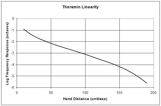
The capacitance change is a function of several things, one of these being the proximity of any conductive object which is in the circuit - for a theremin this is any object coupled to ground.. As the object approaches the antenna, the capacitance increases non-linearly (in fact its an inverse square law when moving away from the antenna, as in, capacitance decreases in an inverse of the square of the distance) - so one gets a dramatic increase in capacitance close to the antenna, and less rapid decrease as the object moves away from the antenna.

Our response to pitch change is exponential - Every raised octave constitutes a doubling of the frequency of the octave below it.. The reference oscillator is tuned to exploit the fact that capacitance increases non-linearly as the hand approaches the antenna - as in, it is tuned so that the (audio) difference frequency increases as the variable oscillator frequency decreases - and the variable oscillator frequency decreases as the antenna capacitance increases.. Thus the audio pitch (the difference between the variable and reference oscillator frequencies) increases as the hand approaches the antenna, and the rate of pitch increase also increases as the hand approaches the antenna..

However, for musical intervals, the inverse-square law is not correct - (the rate of pitch increase as the hand approaches the antenna is too great - causing compression of the playing area / notes at the high end, and expansion [widening] of the spacing of notes at the low end) , it is orders of magnitude better than if one had the pitch rising as one moved ones hand away from the antenna (such an arrangment is absolutely unworkable) but to get a reasonable number of playable octaves with evenly spaced musical intervals, one needs to "correct" the inverse-square relationship and turn it into an exponential relationship where the audio frequency doubles over a fixed distance of hand movement towards the antenna - and (for a perfect theremin - which does not, and probably cannot exist - at least not without active "intelligent" compensation) this fixed distance should be the same over the whole playing area.

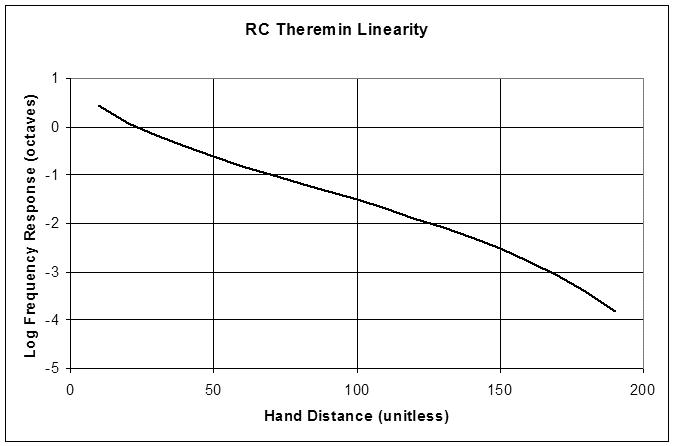
{  The above is simplistic, because the oscillator frequency may not reflect capacitance exactly - there are different responses for different oscillator types - for example, an RC oscillator will relate directly (f = R*C)  wheras a LC oscillator frequency could have a formula like f=1/(2pi(Sqrt(LC)))  And I believe that the Sqrt function does improve the linearity - as in, its certainly better than an RC oscillator -    }

To achieve this, a secondary resonant antenna circuit is added to most high-end theremins and even some not-so-high-end theremins. Thierry has given a brilliant explanation of this mechanism -

http://thereminworld.com/Forums/T/28530/antenna-tuning?Page=3

The above link is to 3 sequential posts by Thierry - I think there should be some "bookmark" for these posts, or that they should be copied into a reference document in the "tech + DIY" section of TW, as they are a masterpiece!

Fred.

Just to be pedantic (LOL - I must always introduce something pedantic ;-).. "Linearity" is a confusing and probably technically incorrect term for what we want.. We want "percieved linearity" - because we are intrinsically "non linear" in the way we percieve sound - both for pitch and for volume.

Posted: 10/23/2012 9:25:34 PM
dewster

From: Northern NJ, USA

Joined: 2/17/2012

Capacitance of an antenna due to a hand in proximity:

Chand = pi*epsilon0*L / (10*ln(4*x/D))

where:
L = length of antenna in meters
D = diameter of antenna in meters
x = distance from hand to antenna in meters
epsilon0 = permittivity of free space = 8.85E-12 Fm^-1

So you have a 1/ln(x) relationship.


Resonant frequency of an LC tank = 1/(2*pi*((L*C)^(1/2)))

Which is a 1/(C^(1/2)) relationship.


Together these give you a 1/([1/ln(x)]^(1/2)) relationship.


This is a frequency, and this needs to be subtracted (heterodyned) from a fixed slightly higher frequency so that you get an increasing audio difference tone with increasing capacitance.

Anyway, stick all this in Excel or similar and you get this (with log2 vertical axis because we sense pitch logarithmically):

Which gives you roughly 3 octaves of something like linearity and, cramped notes near the antenna.

Perhaps Thierry could explain the use of linearizing inductors.  I can only say that they generally increase voltage swing at the antenna (and therefore presumably SNR) and sensitivity which can expand the physical playing range, but I haven't seen much if anything in the way of linearity improvement with them in my simulations.  In designs where the linearizing inductance is much larger than the tank inductance, the linearizing inductor with hand capacitance form the dominant resonant structure, with the tank mainly stimulating it and sensing its resonance point.

*ring* Class dismissed!

(oops, FredM beat me to it)

Posted: 10/23/2012 9:28:04 PM
RoyP

From: Scotland

Joined: 9/27/2012

Fred,

thanks for your reply and yes, I was asking about the principle underlining the linearity although after reading your reply and looking at Thierry's posts that you linked to, I'm kind of thinking that I should really have had a nice cup of tea and listened to some early Kraftwerk instead.

Seriously though, I had an idea that the inverse square law was in there somewhere and your linkage of this with the incongruous nature of musical intervals started to make sense to the question.

I've read Thierry's posts a couple of times and will do so again when I dont' have a headache and tired eyes.

From what I can understand over these first readings I sense that the answer to my question is indeed over this page and the link you have posted!

Thanks muchly!

Roy


PS-I guess that if it was easy then we'd have theremin with perfect linearity by now...

Posted: 10/23/2012 9:37:16 PM
RoyP

From: Scotland

Joined: 9/27/2012

Dewster, thatnks for that: a picture is worth a thousand words although a good equation or two definitely helps. It's making sense now although I WILL revisit this page and it's link again to make sure I understand what you all are saying (pedant alert...what you all are typing).


'"Linearity" is a confusing and probably technically incorrect term for what we want.. We want "percieved linearity" - because we are intrinsically "non linear" in the way we percieve sound - both for pitch and for volume' - Fred

Yes I can see how that would be the case.


Roy

Posted: 10/23/2012 9:47:56 PM
FredM

From: Eastleigh, Hampshire, U.K. ................................... Fred Mundell. ................................... Electronics Engineer. (Primarily Analogue) .. CV Synths 1974-1980 .. Theremin developer 2007 to present .. soon to be Developing / Trading as WaveCrafter.com . ...................................

Joined: 12/7/2007

"I'm kind of thinking that I should really have had a nice cup of tea and listened to some early Kraftwerk instead." - Roy

LOL ;-) - Man, do I know that feeling!

To be honest, until I got into theremins, my encounters with the exponential nature of pitch was limited to voltage-controlled oscillators and filters.. Theremin takes this fairly minor "can of worms" and turns it into a worm circus!

"  Perhaps Thierry could explain the use of linearizing inductors.  I can only say that they generally increase voltage swing at the antenna (and therefore presumably SNR) and sensitivity which can expand the physical playing range, but I haven't seen much if anything in the way of linearity improvement with them in my simulations." - Dewster

I dont understand that at all! - I have run your spreadsheet and seen huge improvement in linearity with correctly selected tank + linearizing components - Provided one has the linearizing resonator acting as a 'virtual inductance' across the tank inductance, it works.. What am I doing wrong !? LOL ;-)

Posted: 10/23/2012 9:48:24 PM
dewster

From: Northern NJ, USA

Joined: 2/17/2012

Roy, here's the quickie spreadsheet if you want to play around with it (nothing in it except for the 1/([1/ln(x)]^(1/2)) relationship and the heterodyne subtraction):

http://www.mediafire.com/?po91jsz481rp7zg

I find simulations much easier to grasp than anything else.

Posted: 10/24/2012 4:21:12 PM
dewster

From: Northern NJ, USA

Joined: 2/17/2012

- For the RC Theremin case -

Resonant frequency of an RC oscillator = 1/(2*pi*R*C)

Which is a 1/C relationship.

Plugging in our hand capacitance relationship gives:

1/[1/ln(x)] or simply ln(x).

Heterodyning this gives:

Flocal - ln(x)


When graphed it looks like this:

Which is not all that qualitatively different than the LC Theremin response shown previously.  Interesting.

Posted: 10/24/2012 8:00:07 PM
FredM

From: Eastleigh, Hampshire, U.K. ................................... Fred Mundell. ................................... Electronics Engineer. (Primarily Analogue) .. CV Synths 1974-1980 .. Theremin developer 2007 to present .. soon to be Developing / Trading as WaveCrafter.com . ...................................

Joined: 12/7/2007

"Which is not all that qualitatively different than the LC Theremin response shown previously.  Interesting." - Dewster

Yes, it is interesting.. Something is wrong!  I think whats wrong may be something to do with the "unitless" nature of the above simulation .. Whatever - Build a RC theremin, a LC theremin, and a LC theremin with fully implemented antenna equalizing (LC+).. Then compare them .. The RC will perhaps allow a skilled player to produce a roughly recognisable tune spanning 2 octaves max, and the pitch errors will be painful - one octave will be reasonably playable. A LC will extend this to 3 octaves with a much greater distance between notes and the possibility of a few of the notes being truly on-key .. 2 octaves will be reasonably playable - The LC+ is what we are used to - 5 octaves, at least 3 of which are linear and playable.

So your graph above is either wrong, or not telling the whole story - Running your full simulation, one can see the differences EQ makes IF one selects the best values and IF one doesnt get too greedy - Set the null beyond 60cm and you are being too greedy! ;-)

Fred.

It is important to note that linearity is only consistant if the same null distance is always used - as soon as one decides to move from a null distance of say 50cm to 60cm, the theremin should be re-tuned (as in, the VFO and REF oscs need re-tuning) if one wants optimum linearity.. The same is true for computations - change the null position and you will see that other things need to change for optimum response.. in practice, linearity is never fully optimised anyway, so a few cm difference in the null point wont be noticed.

Posted: 10/24/2012 10:41:33 PM
dewster

From: Northern NJ, USA

Joined: 2/17/2012

"So your graph above is either wrong, or not telling the whole story..." - FredM

Probably a little bit of both!  The hand capacitance change is total, not incremental (hand plus antenna).  And who knows if the ln(x) relationship corresponds to reality.  They make pretty curves though!

The major takeaway here I think is the influence of heterodyning.  Frequency subtraction is a non-linear operation in the logarithmic domain (if I stated that correctly).  As you say, you can get all kinds of curves simply by moving the null point (equivalent to retuning the local oscillator).

"It is important to note that linearity is only consistant if the same null distance is always used - as soon as one decides to move from a null distance of say 50cm to 60cm, the theremin should be re-tuned (as in, the VFO and REF oscs need re-tuning) if one wants optimum linearity."  - FredM

I believe this only applies to designs that have linearizing coils that are quite a bit larger (i.e. quite a bit more inductance) than the tank coil - you have to tune everything else to accommodate that resonance.  With no linearizing coil, or a linearizing coil on the order of the tank coil, probably only the local oscillator frequency needs adjusting.  This is a major design decision IMO because it very much impacts the effort and expertise needed for factory and subsequent field calibrations of the pitch section.

You must be logged in to post a reply. Please log in or register for a new account.