Digital Dynamics

Posted: 11/23/2013 12:07:47 AM
FredM

From: Eastleigh, Hampshire, U.K. ................................... Fred Mundell. ................................... Electronics Engineer. (Primarily Analogue) .. CV Synths 1974-1980 .. Theremin developer 2007 to present .. soon to be Developing / Trading as WaveCrafter.com . ...................................

Joined: 12/7/2007

I suspect that this could turn into a controvercial thread, but at the outset, I want to say that its not meant to 'dis' digital - and that I probably dont know what I am talking about in this posting... I just have some ideas and hypotheses I want to share - But most of all I probably have big gaps in my understanding, and I have questions I am sure others here will be able to answer. I am not actually "asking" any "questions" - I am presenting what I think - The "questions" are implied because I am not sure if what I am postulating is valid.


This thread was "inspired" by comments on the open.theremin thread. -

When I say "is" or make any 'declaration' in the following, please understand that this is not a statement of "fact" - I could be wrong about any assertion or calculation I make.. This is NOT my area of competency!


I want to start by ignoring issues such as aliasing etc (although others are welcome to tread this route here) and just look first at the issues which bother me and cause me questions - It may well be that the answers to my questions are embedded in deeper matters which I have not fully understood, and that those answering will need to go into more depth and maths than I would like - but please do - I will try to keep up!


Dynamics:


With a musical instrument employing digital production of the sound (which ends up as a digital word being fed to a Digital to Analogue Converter [DAC]) the output waveforms resolution is defined by two factors:

1:) The number of samples output per second, for example, 48ksps = 48000 samples per second, and

2:) The dynamic level  resolution, or how many voltage steps the signal has - for example, 8 bit resolution = 256 steps, 12 bits = 4096, 16 bit = 65535.

My problems / questions are related to the effect on the quality of the waveforms reproduction as dynamics of the signal (amplitude of the waveform) is varied by computation, in order to produce the "envelope", and the resulting loss of resolution for any waveform which is having its amplitude altered by digital computation.

Lets take a sine wave with 12 bit resolution - at full output level one gets a highly respectable 4096 step reconstruction of this wave. If one has a volume controller (envelope generator, volume antenna, whatever) acting on this signal before the D/A (as in, dividing the level of each value being fed to the D/A to exert control of the output) then each 6db drop in volume equates to an effective loss of one bit in that waveforms resolution - so:
-0db (full volume) = 12 bit = 4096 steps; -6db = 11 = 2048; -12db = 10 = 1024; -18db = 9 = 512; -24db = 8 bits = 256 steps...


From the above, it can be seen that as  the attenuation applied by the controller function gets to -24db, the resolution of (an originally 12 bit) waveform will have dropped to 8 bits.. My expierience is that (to my ears) 8 bits still gives just about acceptable resolution for signals which are not too complex..


But when a complex waveform  goes below about 8 bits, I really start to notice it – I think that what happens is this:

Any components of the waveform which are below the level of the possible resolution of that waveform, are lost – lost, essentially, due to the quantizing, in the noise floor – results which sit between two bits “steps” will be either “assigned” to the lower or the higher step – At best, there is a 1 bit noise ‘jitter’ – so as the waveform is divided by the dynamics operations, the resolution of the lower quantity components are affected more severely – and as (with most waveforms) it is the higher harmonic components which are at lowest amplitude, it is these which get lost most rapidly into the noise floor –


With an 8 bit waveform, one can resolve components perhaps down to -42db, a 6db reduction in this waveform (down to 7 bit) and components below say 36db will be lost.. Oh, there will be a 6db reduction in all components of the waveform – but components which drop below the noise floor are lost – they are gone – And to my ears, an 8 bit waveform subjected to digital (computed)  amplitude control sounds as if a noisy low pass filter is being applied as the level is reduced.

  Most of what I say here is based on memory of my experiments in the late ‘70s / early ‘80s when I was designing and building synthesisers – Like many at that time, I was exploring digital waveform generation / wavetables etc.. And I was using ancient clunky components I could afford.. 8 bit DAC’s like the DAC0800 were ideal as one could buy compatible 8 bit static RAM and EPROM on 0.1” pitch  and build a whole wavetable DCO using a simple 8 bit processor or even using standard logic..

I appreciate that nobody is proposing an 8 bit computed digital musical instrument! ;-)


But it seems to me that the reduction of fidelity must apply regardless of how many bits are employed for the wave table – ok, the difference is that if one starts with a 16 bit waveform, one has an extra 42db’s “headroom” before one gets to 8 bit resolution.. But as the computed level drops, the quality of the waveform is degraded.. The only important issue is whether this degradation becomes audible, or whether it only starts to occur at levels where the sound is inaudible.

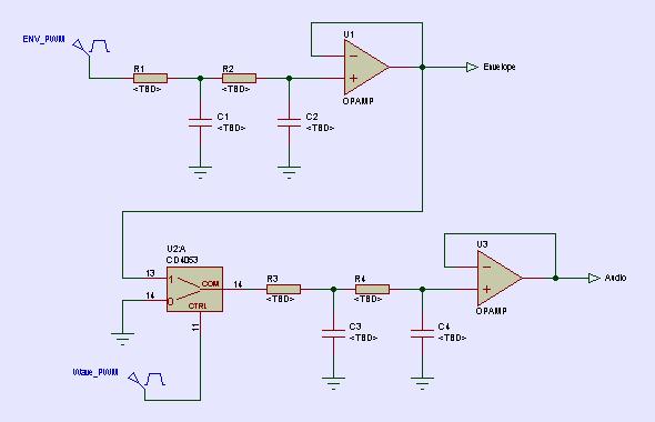
In order to get reasonable fidelity from my synth, I first used mixed signal (mixed analogue and digital) techniques, having an 8 bit MDAC outputting the waveform, and controlling the amplitude from an analogue signal (voltage) – Then used two DAC’s (one as an MDCAC for the waveform, one to control dynamics) – this method results in a waveform which does not degrade as the amplitude is changed.

Looking at the open.theremin, I wonder if using two 12 bit DAC’s in a similar manner might not give far better sound quality than increasing the digital resolution to say 16 bits could.
A small diagram here shows the idea.

Fred.


Posted: 11/23/2013 12:43:04 AM
dewster

From: Northern NJ, USA

Joined: 2/17/2012

"I appreciate that nobody is proposing an 8 bit computed digital musical instrument! ;-)"  - FredM

The early Fairlight CMI models used 8 bit samples coupled I believe to 8 bit envelopes, in an analog multiplying scheme like you discuss.  I realize it was technically quite early on, and perhaps not always in the best of musician's hands, but that synth has stunk up the sound tracks of more 80's movies than I care to remember :-)

The use of two 12 bit DACs would probably work fine, provided imaging / aliasing was taken care of.  But there isn't really any need for it.  You rightly point out the effects of the lack of sufficient resolution as one nears the noise floor of even a 16 bit linear audio DAC, but this can be largely overcome with simple dithering techniques.  It may seem counter-intuitive, but with dithering one can statistically resolve below the noise floor.  (The DPLL I use in my Theremin wouldn't work properly without it.)  For example, when mastering a 16 bit CD the truncated bits from mixing are dithered to make the noise floor higher resolution and white.

Noise reduction techniques in digital filters to a first order may be seen as the preservation energy: taking whatever energy is being truncated at the output of the accumulator (the accumulator is always wider than the output), filtering it a bit, and dumping it back into the accumulator to live another day.  Our ears seem quite sensitive to loss of energy distortion.  Handling this energy conservation without introducing significant tones (e.g. low order PWM) is important to our ears as well.

Posted: 11/23/2013 1:32:53 AM
FredM

From: Eastleigh, Hampshire, U.K. ................................... Fred Mundell. ................................... Electronics Engineer. (Primarily Analogue) .. CV Synths 1974-1980 .. Theremin developer 2007 to present .. soon to be Developing / Trading as WaveCrafter.com . ...................................

Joined: 12/7/2007

" taking whatever energy is being truncated at the output of the accumulator (the accumulator is always wider than the output), filtering it a bit, and dumping it back into the accumulator to live another day. " - Dewster

I accept that this sort of thing must work - otherwise we wouldnt be able to listen to digital reproduction as it would sound too horrible..

But I have real problems understanding how it works - yeah, in this area I an just STUPID! - I have read everything about it that I can read and comprehend, and the fog still surrounds me..

You see, my problem is that whatever one does to correct the problems at the accumulator, the accumulator must still dump the data to a DAC of finite resolution, and if this DAC is linear, I cannot see how anything done to the levels in the Accumulator can be output in a way which isnt distorted by the DAC's quantization.. With a non-linear DAC I can see it more easily.

Perhaps it just comes down tp my preferences - The dual DAC scheme suits me because I am a maths illiterate, and the idea of dealing with the complexity of digital filtering, dithering etc is just too daunting - wheras generating two seperate outputs and using one as an analogue control on the other just seems so simple.

Fred.

About 15 years ago I built a motor commutation controller which needed a 12 phase-shifted sine output with master digitally controlled levels - I used my mixed signal method to implement it in a PSoC using 13 seperate PWMS, 1 behaving as a DAC and 12 behaving as MDACs, the motor ran beautifully.. Then (after I left) some digital engineers came and re-engineered the board using a big DSP.. I got a call from the client about 10 years ago because for some reason they could never get the motor to run so smoothly..... Eventually they went back to my board - It was at low speed, when the amplitude was lowest, that the all digital board was noisy.. They HATED having "dirty analogue" on their board - But even with dithering etc and loads of stuff I couldnt comprehend, if youve only got say 8 descreet steps, you cannot produce as smooth a sine as you can with 256 steps! - or you cannot without extensive filtering, and this doesnt work if the motor speed must be variable.


Posted: 11/23/2013 6:02:17 AM
dewster

From: Northern NJ, USA

Joined: 2/17/2012

"I have read everything about it that I can read and comprehend, and the fog still surrounds me.."  - FredM

I know where you're coming from.  It's been a really slow process, and for all my bluster I can't say I completely understand it all.  As in most of science and engineering, the basics can be grasped I think without much or even any math.  I had the standard "fitting the analog filter to the discrete time domain" classes in college (pre-warping, stability, zeros and poles, etc.) and while I encounter that stuff now and then on web sites, I'm not sure it is all that useful unless you are designing super analytical filters, or ones that need to be spot-on in pitch.

Analog filters have voltage dividers in them that are frequency dependent.  The same is found in digital filters, but there it is more problematic because reducing the amplitude of a signal tosses away resolution (and so increases quantization noise).  The higher the attenuation in a digital LPF the lower the cutoff.  So you use wider accumulators to try to track things way below where you will be truncating the output.  There apparently are digital constructs that are better with internal overload and such, the feel for this comes I suppose as you simulate them in Excel or similar.  Obviously filter design is very critical if you are building something like a digital mixing console, where the many filters will be cascaded and combined.  But if you are using only a couple of filters on a single voice I imagine the constraints may be fairly relaxed in comparison.

Like in most things, it's a matter of reading papers and simulating your particular application.  Then reading more papers, etc.  It's a big field and I have been very slow at taking even a small part of it in.  But the more I feel I know about it the simpler it all seems.  We all have to form our own internal unifying concepts, and before that happens we crawl around in the dark for what seems like forever in some areas.

I studied oversampled DACs in grad school, mostly on my own for part of my thesis, so I'm somewhat familiar with what is going on there, but noise shaping still seems a bit magical.  If you read any papers on higher order modulators you'll see a lot of hand waving and seat-of-the-pants stuff going on along with the fancy math.

All this digital stuff is relatively new to engineering, so it's not surprising that it isn't explained very well.  That, and a lot of the filter stuff was proprietary to various synth and effects companies, with some of the real meat not reaching the light of day until Dattorro published his series of papers.  There must be tons of stuff going on for profit that we'll never see.

The math is useful for finding out what the filter coefficients will be given a topology, and for finding upper limits to SNR and the like if quantization noise is treated as white.  It's great for papers where the author needs to really pin something down academically.  For the rest of it's probably just that - interesting perhaps but academic.  I'll most likely be using digital versions of analog filters (IIR) - simple first order, simple second order, and state-variable.  I'll keep the accumulators wide, deal with truncation noise as necessary, and that's probably about it.

Posted: 11/23/2013 6:08:17 AM
FredM

From: Eastleigh, Hampshire, U.K. ................................... Fred Mundell. ................................... Electronics Engineer. (Primarily Analogue) .. CV Synths 1974-1980 .. Theremin developer 2007 to present .. soon to be Developing / Trading as WaveCrafter.com . ...................................

Joined: 12/7/2007

Dewster -

Thanks for reminding me about the CMI! - I have never got hold of service manual / schematics for that instrument - back in the early 80's (well, 1976 to 1983) when I was into that stuff, there was no internet, and even if data was available one had to pay ..

But now, a quick google and its all there, free for the taking! ;-)

The voice cards do exactly what I was doing (except that I mostly used analogue EG's so only had one MDAC), this one http://cmi.fairlightus.com/fairlight_docs/CMI-01.pdf is the earliest, and even used the same horrible filter scheme I first used! - the later one
http://cmi.fairlightus.com/fairlight_docs/CMI-01A.pdf uses the much better analogue SSM chip.

Looking over the other schematics, I realise that the digital stuff could probably all quite easily be 'cloned' into a single PSoC or FPGA.. Perhaps the whole thing could even be built as a module for the EuroRack mob to put in their setups....

NO!  - LOL ;-) Too tempting to take on yet another project for all the wrong reasons...

Fred.

Posted: 11/23/2013 6:19:00 AM
dewster

From: Northern NJ, USA

Joined: 2/17/2012

"Too tempting to take on yet another project for all the wrong reasons..."  - FredM

Some small part of my brain wants desperately to do a DX7 (or better) in an FPGA.  Probably better off in a DSP, but it would be interesting see if it could be done, and how big the FPGA would have to be.  Afterward I could bask in cheesy, cloyingly sweet electric piano and bell sounds.

Posted: 11/23/2013 2:43:24 PM
gaudi

From: Switzerland (CH)

Joined: 8/6/2010

Excellent idea I think, Fred. I could even imagine to generate the waveform with 8 bit (even PWM as I did on an early open.theremin - works well for smooth waveforms) and control a subsequent amplifier with 12 bit DAC.This would probably give much better noise to signal ratio too.


Posted: 11/23/2013 6:13:41 PM
FredM

From: Eastleigh, Hampshire, U.K. ................................... Fred Mundell. ................................... Electronics Engineer. (Primarily Analogue) .. CV Synths 1974-1980 .. Theremin developer 2007 to present .. soon to be Developing / Trading as WaveCrafter.com . ...................................

Joined: 12/7/2007

Hi Gaudi,

I found (with more recent experiments) that 10 bits for both was (at that time) the best price / performance ratio .. 8 bit waveform was JUST acceptable to my ears, 8 bit linear volume control was too rough - was ok if I fed the envelope through a log converter first - and this is easy, just a couple of transistors and an opamp.

I wasnt at all happy with 8 bit PWM waveforms, but I seem to remember that I was limited to something like 33kHz for my PWM, so it was probably just that.

I notice that the later Fairlights went over to 16 bit, but still retained seperate waveform and envelope DAC's, and used VCA's rather tham MDAC's.

By far the simplest possible dual DAC scheme that I have ever used is shown below - I have used this principle on all sorts of designs.. The actual schematic is just conceptual - I usually implement active integrators / filters. The 4053 forms a switching PWM integrator, and the envelope determines the incoming charge voltage and therefore the amplitude of the waveform being output.. If you have a fast enough PWM you can implement however many bits as can be managed. (with a PSoC_1 I can get 10 bit resolution at 48kHz clocking the PWM a little over 48MHz - but one of those bits is probably "lost" in jitter and integrated by the 4053, so its more like 9 bit resolution - however it sounds better than clocking at 24MHz and implementing 9 bits)

Fred.

Top Left input = Envelope PWM input, Bottom Left input = Waveform PWM input.

Top Right Output = Analogue Evnelope / level control, Bottom Right Output = Analogue waveform with its level controlled by the analogue Envelope.

ps .. In real life I tend not to use direct PWM signal from a processor or logic part - CMOS is quite clean, but if one has any noise on the digital PSU, this gets integrated with the PWM and can cause bother.. So I tend to use CMOS switches or transistors powered from a seperate clean analogue regulator, even if I dont need a MDAC function. (there are 3 independent switches in a 4053, so I generally use these - tend to use the 74HC or HCT variants.. HCT if my PWM is below 5V - say 3.3V - as I can then still run the 4053 from 5V.. Also, the 4053 has a lovely level converter built in so your analogue can have a bigger voltage swing)

I have found that with seperate envelope and waveform 'paths' I get a sound that is much more "analogue" to my ears, its not just about SNR (in terms of overall SNR, I dont think there is any real gain in this route if one is using say a 16 bit digital system) - I think its about where the noise is placed, and the effect of limiting waveform distortion even when the waveform sinks into the noise floor.

One of my present projects is employing a lot of the above stuff - I am generating a harmonic series, and need to have control over the level of each harmonic.. but the fundamental is somewhere above 100kHz and the frequencies are all constant.. I am using the 4053 trick, but not driving it with PWM, just driving it with a square wave at the required harmonic frequency - I can therefore control the amplitude of this square wave, and feed this to a filter to convert it to a sine.. The 4053 is a great way to modulate the amplitude of a logic level output from a MCU or whatever.- A LOT simpler and cheaper than having a load of HF VCA's!

Posted: 11/23/2013 6:20:38 PM
dewster

From: Northern NJ, USA

Joined: 2/17/2012

gaudi, do you own a copy of "Musical Applications of Microprocessors" by Hal Chamberlin?  It's a bible of sorts for anyone doing sound synthesis in HW/SW.  A bit dated, but I've never encountered anything quite like it.

Anyway, he discusses and address aliasing a fair bit.  One quote:

"One of the big problems with the generation of tones of arbitrary frequency and waveform is the avoidance of alias distortion.  As it turns out, it is quite possible, sometimes unavoidable, to digitally generate a tone having frequency components above one-half the sample rate.  When this occurs, the higher frequencies are reflected down at lower frequencies that then sail right through the DAC's low-pass filter, no matter how sophisticated."

When I read this for the first time it was quite an eye-opener for me.  It's really bad news for digital synth designers as it makes our jobs a lot harder.

Posted: 11/23/2013 6:51:32 PM
FredM

From: Eastleigh, Hampshire, U.K. ................................... Fred Mundell. ................................... Electronics Engineer. (Primarily Analogue) .. CV Synths 1974-1980 .. Theremin developer 2007 to present .. soon to be Developing / Trading as WaveCrafter.com . ...................................

Joined: 12/7/2007

"Some small part of my brain wants desperately to do a DX7 (or better) in an FPGA." - Dewster

LOL ;-) .. The above just highlights our differences! ... I would be utterly clue-less, its taken me years to get a handle on how to work with those damn FM operators, the idea of actually implementing a digital 'clone' of the DX7 is in about the league of designing a time machine, to me!

"It's a bible of sorts for anyone doing sound synthesis in HW/SW.  A bit dated, but I've never encountered anything quite like it."

I completely agree with you! - By far the best book on synth technology (and general related electronics) both digital and analogue, that I have ever found - And I have a bookshelf full of great books!

I wish there was a later version which looked at stuff like FM and LA etc.. But in some ways I am glad its limited to earlier (IMO more intuitive) stuff.

Fred.

You must be logged in to post a reply. Please log in or register for a new account.