Dewster:
1. Use a standard LC oscillator for the pitch side.
2. From (1) somehow obtain a number that corresponds to hand location.
3. Run (2) through a mathematical function.
4. Use the result of (3) to generate an analog waveform.
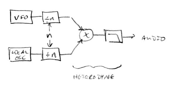
5. Heterodyne (1) and (4) together with an analog mixer to get audio out.
Its obtaining the "number" and processing this which is the crunch - its dead easy when one has this with high enough resolution, to generate a HF "variable oscillator" waveform and a "reference oscillator" waveform out, and do analogue heterodyning on these.. If one has a digital processing scheme, one can simply output a reference square wave (say 250kHz) and generate a VFO square wave (say from 244kHz to 250kHz, or whatever span one chooses), put each of these through a LC filter tuned to say 247kHz, (or more elegantly, through a variable HF LPF/BPF to adjust the harmonic content) and get two sines out that can be analogue heterodyned.
As I see it, there is no need to heterodyne 1+4, doing so will (as I understand it) greatly complicate the maths required in (3) if (1) is variable frequency - I would want (3) to process the linearity curve.. and this is only "easy" if one has a constant against which to apply the function (or at least its easier to me ;-).
Heterodyning 1+4 is effectively what I am doing with my "upside down" topology, but this only works because (1) is in a PLL so its locked to a constant reference frequency - the analogue computed maths takes the "number" (2) from the PLL and runs it through a mathematical (analogue) function (3) the result of which controls a HF oscillator (4) which is heterodyned with the same frequency as (1).
I have recently (almost) decided that I dont need a PLL locked antenna oscillator - that I can simply drive an antenna LC with constant reference frequency, derive a CV from this in a similar manner to volume antenna circuits, process this voltage (linearity, span etc) and use it to drive a HF VCO which is mixed with the reference oscillator - The maths function becomes a little more complex, but this is more than compensated by removal of the antenna-side oscillator and PLL..
Added ->
"I think the idea is crazy because the player would likely audibly detect the various lags in the response of the various processes. And it's not as straightforward as just proceeding digitally from (2)." - Dewster
In essence, I dont see the idea as crazy at all - If one can get the 'numbers' fast enough and with high enough resolution, there is absolutely no reason not to produce HF signals based on this and perform analogue heterodyning on these.. No extra processing overhead would be required, and one could have a hybrid digital theremin outputing true heterodyned audio (as well as whatever other wavetable or "digital" output you choose)..
ok, disclosure time ;-) .. I am looking at FPGA to implement register switching and "mixed signal" heterodyning - I am looking at 3 voices - one being true, pure analogue heterodyning which isnt messed with by the FPGA in any way and doesnt switch registers - it stays at its natural pitch regardless of the register setting and is purely analogue derived directly from the reference and variable oscillators..
Then the FPGA processes two register switches which can be locked together - these control two seperate voices, one being my mixed signal voice, the other being another analogue heterodyning mixer driven from signals generated by the FPGA and filtered (external to the FPGA probably with LC - but register switching is giving some headaches here as this idea requires switching capacitors in these filters) to produce sines / modified sines from square waves.. I might dump this voice if it becomes too complex / costly.. But if I do dump it, I will probably dump the FPGA - It wouldnt be doing enough to justify its expense (unless I implement a DUI).. And I am balancing between FPGA and PSoC.. FPGA gives more possibility of other intervals, PSoC is home ground...
All voices would be locked to the "natural" voice but can be shifted in (as yet to be confirmed - certainly octaves up / down, but hopefully some other musically useful) intervals reletive to the natural voice. The tonal charactaristics and levels of each voice independently controllable.
Fred.