My New Year gift to TW: A new theremin circuit

Posted: 1/4/2014 8:16:31 AM
Thierry

From: Colmar, France

Joined: 12/31/2007

Let's start with the last question: if you say breadboard, does that mean one of these white solder free ones where 5 or more contact holes are always connected together? A such one wouldn't work, too much parasitic capacitance. But if you mean a circuit board with holes and round copper dots in 0.1" spacing, it will work and you can use the same component layout as on the PCB which is shown in my posting.

1n5 is 1.5nF or 1500pF, yes.

The audio out has line level and high impedance and thus can not drive a speaker directly. It is intended to be connected to the inner wire of a shielded cable (shield connected to GND) which transports the signal towards an external amplifier.

Posted: 1/4/2014 9:43:12 AM
TheIMUman

Joined: 1/3/2014

Thank you, that answers it. I can follow the layout and use a(round hole) perf board.  I looked for the 2N5484 at mouser and it's "no longer available" but I found it on ebay no problem. 

I also happen to have a little $3.00 amp that I wired up to some speakers that I plug into my computer.  It runs off a 9V or my salvaged flat panel monitor power supply.  I tried powering it by USB and it sounded like a machine gun.  It sounds great with its own power though.    

Posted: 1/15/2014 10:46:37 PM
Leon Pijpers

Joined: 1/15/2014

Hi,

Using some parts I had available I managed to make a modified version of your design.

For the jFET I used the 2N4393 (TO-18 metal can TH version, a bit expensive($2, 25+), but there is a TO-92-3 version which is a lot cheaper MPF4393RLRPG ($0.244 10+) and a SOT-23 SMD version MMBFJ309LT1G.

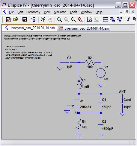
Also the 1mH coil was not available, so i used the largest wire-wound coil I could find, a 330uH type with about 0.6 Ohm DC resistance, and simulated one sine wave oscillator in LTspice.

I checked other jFETs also in simulation, U309 works also, but is also an expensive metal can type. the J309G TO-92 TH type is a lot cheaper, and there is a SOT23 version type MMBFJ309LT1G.

imagine here a picture of the

simulation of one sine wave oscillator

On experiment/perforated board I built both oscillators and the add/subtract part, without bothering to simulate the complete schematics. after correcting some solder joints both oscillators worked. After figuring out which oscillator should have the highest frequency, I added 2 extra variable capacitors on the other oscillator. Without them the output frequency got lower as my hand got closer to the antenna. With the extra capacitors the frequency got higher. My antenna was also only a thin wire, and sensitivity is still low. But for a first try I am pretty pleased with the results. putting everything in a box with a bigger antenna, could improve the results a bit.

If it works I try to add a picture here, or in the Photo album of simulation and the prototype pcb.

Picture:

my first working theremin (pitch only)

Because of the smaller coil value I experimented with a little higher capacitor values an smaller resistors, it is not too critical. With the original values it works also with the 330uH coil.

Picture:

the ugly bottom ;)

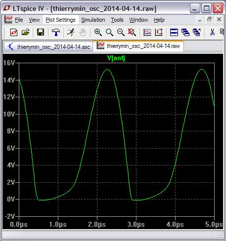
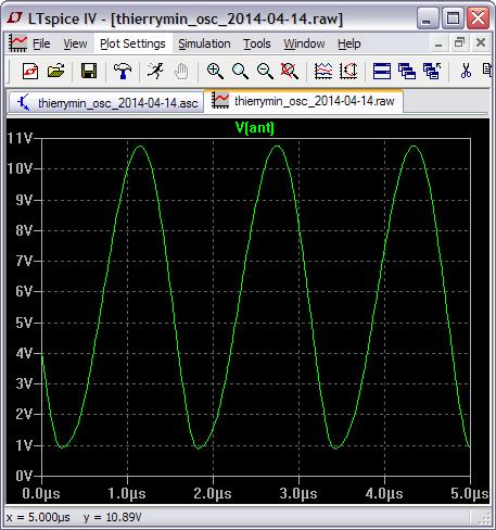
To get cleaner sine wave shape I added a capacitor parallel to the inductor, value 100pF which seems to give me a better shape on the oscilloscope. in LTspice (www.linear.com) a value up to 470 pF seems to make the shape better. I'm not sure if the sound gets better with better sine waves of the 2 oscillators. When they get mixed, it becomes a complex shape anyway.


I also experimented with Wien bridge oscillators using LM324 or LM358 op-amps, they just are much too slow.

Even TL072 is not fast enough. The slew rate is too low. (also the Gain Bandwidth is not high enough of some.)

AD547 is fast enough, just costs about $5 for one IC! Other IC's weren't available.

So I was very happy find Thierrys new years present.

Finally I have a working Theremin (pitch only)!  

Next on the todo list to get the volume part working.

Thanks Thierry, and good luck to all experimenting with theremins :)

Posted: 3/24/2014 1:30:13 PM
Mactron

From: Bradenton, Florida

Joined: 3/23/2014

I just wanted to thank you for the theremin circuit.  It worked quite well in an old wooden D.C. meter box. I had no issues procuring the parts. I was able to cross reference the out of date transistors with the NTE 451s at less than $2 each.  The 10 mH inductors were readily available as well.  I used the very small ones (about the size of a 1/4 resistor) with no problem because of the low current requirement and relatively inexpensive. I was unable to place the AC power supply within the box as it introduced too much capacitance. The box is only about 20 cm square, so there is not a lot of room to separate items.  I used a 43 mm by 71 mm pre-etched project board with no problems. I am working now to isolate the line output so as to reduce the addition of capacitance. Feeding an external amplifier or system requires me to do some major re-tuning. I had considered originally making a permanent connection to ground through the safety ground on the power cord.

Posted: 4/14/2014 9:52:20 PM
dewster

From: Northern NJ, USA

Joined: 2/17/2012

Thierry, thanks for sharing your oscillator!  I just spiced it in hopes of better understanding it:

The antenna voltage looks really rounded on the bottom, which I wasn't expecting (however there is a very nice sine wave at S1).  The antenna voltage looks more like a sine wave if C2 is made the same as C1 (150pF) but this reduces antenna voltage swing:

Maybe my 2N5484 model is off? 

.MODEL 2N5484 NJF(Is=.25p Alpha=1e-4 Vk=80 Vto=-1.5 Vtotc=-3m Beta=3.0m
+Lambda=10m Betatce=-.5 Rd=10 Rs=10 Cgs=4p Cgd=4p Kf=3e-17)

It indeed oscillates around 410kHz with a 10pF antenna, and draws around 1.25mA from the supply (in simulation, I haven't breadboarded it). 

LTSpice file is here: http://www.mediafire.com/download/i482ql2mfy2kfcb/thierrymin_osc_2014-04-14.asc

There's no law that says antenna voltage needs to be perfectly sinusoidal, but a good sine is one indication of a lightly loaded tank.

Posted: 4/14/2014 10:11:59 PM
Thierry

From: Colmar, France

Joined: 12/31/2007

Hi dewster, the NJF model seems correct to me. But the waveforms of your simulation do not forcibly correspond to reality. In reality there is a ~10Vpp sine swing at the antenna with a little distortion at the bottom but not as obvious as in your simulation, centered around +5.9V. Your simulation does not take into account the additional load of the mixer through the 3.3p capacitor and perhaps also not the 3.2Ohm series resistance of the 1mH coil, which could explain the differences.

The bottom distortion of the RF waveform doesn't play a role since the mixer fet is biased is a way that only the positives halves will go through and contribute to the AF wave form.

Posted: 4/15/2014 1:58:44 AM
dewster

From: Northern NJ, USA

Joined: 2/17/2012

"Your simulation does not take into account the additional load of the mixer through the 3.3p capacitor and perhaps also not the 3.2Ohm series resistance of the 1mH coil, which could explain the differences."  - Thierry

I added the the series resistance to the simulation but it doesn't seem to change anything.  Adding an extra 3.3pF to the antenna doesn't change anything either.

"The bottom distortion of the RF waveform doesn't play a role since the mixer fet is biased is a way that only the positives halves will go through and contribute to the AF wave form."

Since they are added together before the clipping, it seems the bottom of the waveform could still play a role in the output.  But what interests me is that the distorted bottom shows a strong drive interaction that I haven't seen in any other LC oscillator.  Not saying it's bad, it just seems kind of odd.

If you see 10Vp-p and only a bit of flattening in real life then it's probably a drive issue in the simulation FET (mismatch with reality).

Posted: 8/18/2014 11:30:43 AM
xtheremin8

From: züriCH

Joined: 3/15/2014

hello engineers and other therepathics,

so finally i'll try to build one of these as a present for my friend, who can't solder. is there a b.o.m ( bill of material) with more specifed infos on what kind of  parts used? capacitors come in different types and made of different materials, resistors are made of carbon or metalloxyd with different %-values.

 thierrys beautiful work is allways recommended as a good starter project, but i missed always that info.

so i still recommend art harrisons designs for starters. imho.

dani

Posted: 8/18/2014 11:57:43 AM
Thierry

From: Colmar, France

Joined: 12/31/2007

Hi Dani,

I didn't think that a detailed bill of materials was needed, because the circuit is so simple and self-explaining. The 3p3, 150p and 1n5 capacitors are all cheap ceramics, the others are electrolytics as shown in the schematic. No special requirements for the resistors, I build these circuits with whatever I can find in the junk box. Carbon or metal film doesn't matter, a tolerance of 10% is still ok, seen that the FETs have a +/- 50% tolerance for I_dss and U_p...

Posted: 8/18/2014 12:52:23 PM
xtheremin8

From: züriCH

Joined: 3/15/2014

thierry,

thanks for your response.

You must be logged in to post a reply. Please log in or register for a new account.