My New Year gift to TW: A new theremin circuit

Posted: 9/11/2016 5:46:18 PM
oldtemecula

From: 60 Miles North of San Diego, CA

Joined: 10/1/2014

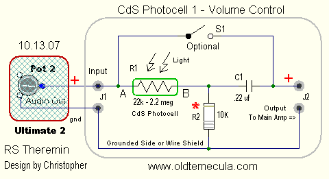
Мартель у вас отличные результаты. Для регулировки громкости можно разместить компакт-диски фотоэлемента между выходом термен и усилитель или Звуковая карта.

Martel you have excellent results. For volume control you can place a CDS photo cell between the theremin output and the amplifier or sound card.

Christopher

Posted: 9/11/2016 5:55:53 PM
Martel

From: Russia

Joined: 9/8/2016

 Martel you have excellent results.

........................................................................

 wonder whether it is possible to remove the distortion in the lower range? Or is it inevitable?


As for the volume level agreement management. Photoresistor allows for simplified volume control.

I do so, and the standard volume control blocks FET.


Posted: 9/11/2016 7:02:09 PM
ILYA

From: Theremin Motherland

Joined: 11/13/2005

Martel,
your "dirt" is the increased phase noise of the beat frequency caused by overcoupling. A common phenomenon.

Does your PCB matching the Thierri's design?

Posted: 9/11/2016 8:24:35 PM
Thierry

From: Colmar, France

Joined: 12/31/2007

Since the coupling capacitors are only 3.3pF, over coupling should not happen if you use the original 2N5484 FET transistors. Other FETs with weaker forward trans conductance and higher cutoff voltage may lead to undesired side effects.
Posted: 9/11/2016 8:32:10 PM
Thaddeus

Joined: 8/2/2016

I have just finished building this design on breadboard now and am running it through a breadboarded LM386 amp. however, the range is very small and high pitched. suggestions?

Posted: 9/12/2016 10:12:42 AM
Thierry

From: Colmar, France

Joined: 12/31/2007

See my replies in the other thread you opened. There is a recommended circuit board layout which should be respected, breadboards have often too much parasitic capacitance. Second, there are recommended antenna dimensions and mounting instructions with the same intent: to minimize static and parasitic capacitance and to maximize the capacitive effect of the hand onto the antenna. Third, after setting everything up correctly, the circuit has to be meticulously tuned with the help of the variable capacitor and by varying the length of the telescopic antenna by a few 1/10 of mm. The tuning instructions are in the very first post of this thread:

"As a pitch antenna, a telescopic antenna with a diameter of 6mm (1/4") and a length of 50cm (20") works best. After building the circuit and installing it together with the pitch antenna in whatever non-metallic housing, pull the segments of the telescopic antenna fully out, but not the last (thinnest) one, which should be pulled out only at the half of its length. Now adjust the variable capacitor for a decent pitch field with the zero point at about 50cm (20") from the antenna. That was the coarse pitch tuning. Fine tuning can now be done by pulling out or pushing in the last antenna segment by a few millimeters until you get a pleasant field geometry and tone spacing."

If the circuit can not be tuned this way, that means that there is something wrong, either with the capacitive behavior and environment of the antenna, or with the circuit, i.e. using coils with too high parasitic capacitance or a bad circuit layout. That's why I posted a layout which works for sure.
Posted: 9/12/2016 5:51:57 PM
Martel

From: Russia

Joined: 9/8/2016

 "Does your PCB matching the Thierri's design?"

No, my charge, but subject to the rules of construction of the theremin.

........................................


"Since the coupling capacitors are only 3.3pF, over coupling should not happen if you use the original 2N5484 FET transistors. "

Yes, I try to replace the mixer transistor 5484 and see if anything changes.

 ........................................

" however, the range is very small and high pitched. suggestions?"

 Inductor what? It is important.

Posted: 9/12/2016 6:11:40 PM
Martel

From: Russia

Joined: 9/8/2016

"  For volume control you can place a CDS photo cell between the theremin output and the amplifier or sound card. Christopher"


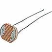
Thank you. I'm developing a volume control on the design of the light detector. And you kind of designs offer? Is there a description of the photo?

 What is the CDS?

Posted: 9/12/2016 6:39:25 PM
oldtemecula

From: 60 Miles North of San Diego, CA

Joined: 10/1/2014

Martel, in my project "harmonic exciter", "FV" is photo-cell. This is a great simple method.

* R2 Optional

Christopher

Posted: 9/12/2016 6:55:54 PM
ILYA

From: Theremin Motherland

Joined: 11/13/2005

CDS=CdS - фоторезистор на основе сульфида кадмия.

You must be logged in to post a reply. Please log in or register for a new account.