


Thanks for that TW link Fred!
Greetings, gots an idea maybe
Posted: 1/10/2014 4:34:47 PM

Yeah, that's impressive.
I've been busy translating French. The planet 4D music theory is some heavy stuff and the originateur actually did earn a PhD from Toulouse institute de Mathematique by developing it. It's interesting that he used a game controller to navigate L'espace de hypersphere. What he did was assign certain chord combinations to vertices of the hypersphere and then the user moved the controller any way he wanted and out popped Jazz or Rock n Roll. This guy beat me to it but I had my idea before ever hearing of his. That's ok and not the first time. It doesn't mean I'll be able to replicate it, but I'll see what I can do and it might even be unique.
Posted: 1/26/2014 1:20:02 PM
My Theremino Master board arrived and I hooked up a receiver. The receiver outputs PWM just like my IMU does. I turned on the synth program and tried to control the signal with a transmitter, but no luck. I used the hardware abstraction layer(HAL) to try different input types and I need to do something to the PWM to make it useful. ADC is one of the input types that the master board likes and I'm thinking I could convert the PWM to an analog signal. One way I could do that is to use the control board from a servo. These little boards receive PWM and convert it to a voltage - that's analog isn't it?
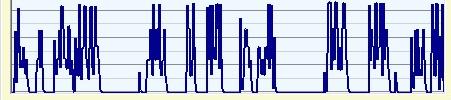
Here's what PWM looks like to the Theremino which probably explains why the only sound I got was like someone banging on a keyboard.

Posted: 2/2/2014 9:07:21 AM
This is where I need some expertise and maybe somebody can help me. The synthesizer program likes a waveform that varies up and down. I started with my signal and it sounded like a monkey banging on a keyboard, so I tried to change the signal with the servo control board and that didn't work right. What I have now is a weak signal that does go up and down, but it needs to be boosted somehow.
Here's the signal it likes:

Here's the signal I have now:

I have a vague idea that I could boost it with an opamp, but I have no clue how I'm supposed to hook one up and set it up. The little PIC board is only supposed to get 3.3V and 100uA, so I'd need to not boost it beyond that.
Thanks for any guidance.
Harry
Posted: 2/2/2014 9:47:27 AM

From: Eastleigh, Hampshire, U.K. ................................... Fred Mundell. ................................... Electronics Engineer. (Primarily Analogue) .. CV Synths 1974-1980 .. Theremin developer 2007 to present .. soon to be Developing / Trading as WaveCrafter.com . ...................................
Joined: 12/7/2007
Hi Harry,
Cannot help at all, sorry - have no idea what those waveforms represent or even if they are "real" - the "PWM" is the sort of thing one sees on a circuit thats entirely dysfunctional - and no idea what those other signals relate to ..
Perhaps someone else can help - but otherwise I think you need to take some time to document exactly what you are doing - block diagrams and/or schematics, detail about known actions / signals, and what produced them etc..
But as I say, someone else may have seen this stuff and know what theyr looking at... PWM is supposed to be logic level, opamps likely arent best to do the job of boosting if its PWM , you need logic buffers or level shifters perhaps.
Cant Theremino help?
Fred.
Posted: 2/2/2014 10:36:13 AM
Fred, the Theremino folks got me this far. They suggested I use a R and C on my signal and ground to take that messy digital looking signal and make it go up and down smoothly like an analog signal. I measured with a voltmeter the high and the low and I get about 150mV on the low and about 400mV on the high. I'm using what I've read is a low pass RC filter. My basic starting signal is 0-5V and I found out it's not a true PWM since it's only on about 6% of the time or every 25ms or so. They told me I need to limit the voltage into to 3.3V and that a 33k resistor would work for that and a 1.0uf capacitor for the on/off.
The signal I need is analog no matter how it starts out. Here's a look at it when I vary the signal real quick. It goes up and down, but comparing it to the signal from a capacitive sensor which is what the synth program likes, it's too small.

Posted: 2/2/2014 12:10:28 PM
From: Eastleigh, Hampshire, U.K. ................................... Fred Mundell. ................................... Electronics Engineer. (Primarily Analogue) .. CV Synths 1974-1980 .. Theremin developer 2007 to present .. soon to be Developing / Trading as WaveCrafter.com . ...................................
Joined: 12/7/2007
" They suggested I use a R and C on my signal and ground to take that messy digital looking signal and make it go up and down smoothly like an analog signal"
PWM should be a constant frequency swinging between logic level 0 (say GND/0V) and logic level 1 (say 3.3V).. The edges should be as fast as possible and as clean as possible, and data is transferred by the mark/space ratio of the PWM (what % of the period its logic 1 vs what period its at logic 0)..
If you dont have that, them you dont have PWM! .... If you slug PWM with an RC filter (integrator) then the DC level will shift - probably screwing things up.
IMO, forget slugging, forget amplifying - get your PWM clean and functional. There is a cardinal "rule" with this sort of thing, it "Garbage in = garbage out" - If you put garbage in, all the filtering and processing in the world wont get as good results as if you didnt put garbage in! ;-)
At best, you perhaps have a mixture of data and garbage going in - putting a simple filter on this will reduce the garbage only if its higher frequency than the PWM (and it looks to me like perhaps you have a load of HF screwing your data) but the filter will also corrupt your data..
IMO, you need to find the problem at source - the source of the PWM! - If the PWM is being generated from a comparator looking at a voltage and comparing that to a ramp or triangle wave, then look at the inputs to that comparator - signals should be clean without noise.. Also, check the power supply - noise on this can screw everything up!
What frequency should the PWM be? What logic levels are specified? Have you looked at the waveforms with a 'scope (NOT a PC 'scope using a soundcard!)? Can you trust what the theremino software is showing you? Are all your grounds solid and connected to a good common ground point? Have you checked that theres no large HF signal source (like a flourescent or "eco" lamp) nearbye?
Alas, this is the sort of problem that a good EE could likely sort out in less than an hour hands-on, but it could take months to do "remotely" and still get nowhere - Also, without good quality equipment, debugging this sort of fault is sometimes impossible -
But whatever - I suspect that you wont really fix it unless you get to its source, and all the hacking in the world upstream will just make things more confusing.
Fred.
This, to me, is unusable as PWM - no matter what the levels are.. there are no identifiable periods and I would be real worried if I had to extract usable data from this - would probably need a DSP and even then not be sure I would get data.. The only hope is that the "low" levels were shunting the noise (it appears that way) and I could derive some periodicity from this - but there are places where the levels etc are so noisy that even this may not give any clues - or certainly not enough to allow simple extraction of data with any usable accuracy.
(this looks to me a bit like something I have seen from a LM393 comparator which was over-driven.. its a common mistake - these parts can misbehave if either input goes above about 2/3 VCC, and they flip output state.. If one has even a slight HF noise on that input, one can get the horrible sort of thing you are seeing here..
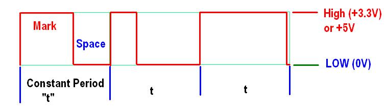
This is what PWM should look like: (with a slow changing signal, you should see the mark widening while the space narrows while "increasing" and the mark narrowing as the space widens while decreasing, but period / frequency and levels should not change.
Posted: 2/2/2014 2:04:48 PM

Hallo!
I am Livio, the ThereminoSystem designer.
The servo signal is not stable and too much slow and noised to play Theremin.
I suggest some alternative solutions:
1) Send IMU data, or 3D software data, directly to Theremino System SLOTS, using a simple software "connector", in your preferred language (C++, C#, VbNet, VB6, Pascal.. and also ThereminoScript). How to write data to our SLOTS is explained here: www.theremino.com/en/downloads/foundations#mmf
and also in the ThereminoScript examples: www.theremino.com/en/downloads/foundations/#script
2) Send IMU data, or 3D software data, directly to Theremino System SLOTS, using MaxMsp as explained here: www.theremino.com/en/downloads/foundations#maxmsp
3) Send IMU data, or 3D software data, directly to Theremino System SLOTS, via OSC messages, as explained here: www.theremino.com/en/downloads/foundations#osc
4) Send IMU data, or 3D software data, directly to Theremino System SLOTS, via MIDI messages, as explained here: www.theremino.com/en/downloads/multimedia#midijoke
Those solutions are very cheap! No Theremino System hardware is required.
Posted: 2/2/2014 2:27:41 PM
There are also other good solutions (but a Theremino Master is required)
1) Connect a very cheap IMU directly to the Master as explained here: www.theremino.com/en/hardware/inputs/accelerometers
(to play Theremin accelerometers are perfect and the signal is very stable)
2) Connect a "ribbon" to one of the six Master PINs, to create a "ThereminCello", "ThereminViolin" or a keyboard like a "Continuum" as explained here: www.theremino.com/en/hardware/inputs/sensors/#pot
3) Connect Potentiometers or Joysticks to the Master PINs, like explained here: www.theremino.com/en/hardware/inputs/sensors/#pot
4) Connect any other sensor listed in this page: www.theremino.com/en/hardware/inputs
5) Buy a cheap RC transmitter on eBay, or use an old device. Remove all the internal electronics and replace it with a single Theremino Master module, connected directly to the potentiometers, as explained here: www.theremino.com/en/hardware/inputs/sensors/#pot
Every sensor suggested in the Theremino System site, is good for the Theremin Synth.
You must be logged in to post a reply. Please log in or register for a new account.