Ethervox MIDI Theremin

Posted: 5/21/2014 1:06:32 PM
dewster

From: Northern NJ, USA

Joined: 2/17/2012

"I just want to build a single oscillator - without any antenna and a reference oscillator. Just one simple Armstrong- oscillator that produces some sound. I am afraid that I dont have more time than that because I should slowly finish the whole presentation... There are only 2 Days to go..."  - synox89

A single Armstrong oscillator that produces sound?  Not sure what the point of that would be.  It would be operating down in the audio range rather than ultrasonic, which would require much larger L & C.  The pitch wouldn't change much with external capacitance.

For simple oscillators, the Theremino Colpitts is hard to beat.   http://www.theremino.com/en/.  The tank is parallel so the self capacitance of the coil won't be as critical (try using whatever you have on hand for L1).  It requires a FET, but just about any NFET will work.  The supply voltage isn't too critical either, but voltage regulation here really helps stability.

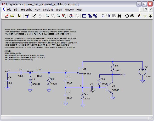
If you want an impressive demonstration of capacitance sensing, build that (you don't necessarily need Q1 or associated components C3, R4, R3) hook a scope probe to the point "S" above, set the trigger delay to something really long like 50ms, and see what effect your hand / body has when approaching the antenna.  C6 is the antenna, and isn't a real component.  C5 can be removed (replaced with a wire) but the oscillator will stall if you touch the antenna.  It won't make any noise without a second oscillator and some kind of mixer.

FredM has given you very good advice, but I fear Theremins aren't something you can come up to speed on in just a few days given your levels of knowledge and experience.

Posted: 5/21/2014 2:46:59 PM
FredM

From: Eastleigh, Hampshire, U.K. ................................... Fred Mundell. ................................... Electronics Engineer. (Primarily Analogue) .. CV Synths 1974-1980 .. Theremin developer 2007 to present .. soon to be Developing / Trading as WaveCrafter.com . ...................................

Joined: 12/7/2007

OT  - Note for other forum users:

This thread is NOT about the Moog Ether-Vox!

Hello again Alex.

Dewster is right "Theremins aren't something you can come up to speed on in just a few days given your levels of knowledge and experience"

If you arent making a theremin, then forget LC oscillators!

This circuit uses a 555 timer IC, and can simplistically demonstrate the sort of waveforms required for violin -

Rgere are two potentiometers, one to set rising time of waveform, the other the falling time - these are limited, so cannot be shorter than about 500us - but one can get triangle waveform down to about 50Hz and ramp down to about 100Hz, and go up to about 1kHz

Both potentiometers will affect frequency.

This circuit is simple and reliable and can be built on plug board - component values are not critical.

"0" relates to wiper being fully up.. headings on 1st  chart is wrong!(should be Rise-100, Fall = 100), but right for other charts.  First chart shows lowest frequency with both pots at maximum (fully down) second shows highest frequency with both fully up.. You can expand the range by making pots bigger and C1 smaller.. The last chart was produced from the circuit with potentiometers  set as shown

Note the scale of the middle chary is 5ms compared to 35ms on the other two.

Its quite a pleasing little circuit because as one changes the frequency with one pot, the timbre changes!

Fred.


Posted: 5/21/2014 4:39:40 PM
synox89

Joined: 11/16/2013

Hey, Fred, this looks really good, its what I needed. One further question: is it hard to alter a Theremin so it has more than one out put (lets say 8), so it has 8x the same tone sounding. Furthermore, the 8 identical notes shouldn't start simultaneously but VERY slightly apart from each other. I speak of  milliseconds. Is such thing feasible?

Posted: 5/21/2014 5:45:14 PM
FredM

From: Eastleigh, Hampshire, U.K. ................................... Fred Mundell. ................................... Electronics Engineer. (Primarily Analogue) .. CV Synths 1974-1980 .. Theremin developer 2007 to present .. soon to be Developing / Trading as WaveCrafter.com . ...................................

Joined: 12/7/2007

Alex - Forget about multiple phase shifted outputs.. Phases need to vary proportional to frequency - A whole different subject more related to string "pads".. If you shift waveforms by a constant time, you end up producing comb filters and the like ;-) (think about it - shift a waveform by 180 degrees and they cancel at a given frequency.. so shift a 500Hz sine by 1ms and add it to its unshifted version, and they cancel out! - and sum at a different frequency..)

Heres an updated schematic, slightly simpler, twice the maximum span (extra octave) and volume control:

R1 -> Not essential, anything <= 100R.. I like 100R because I am paranoid! ;-) I worry about things that "might" happen in near-impossible worst-case scenarios.. like if Q is high and DC is low (which really cannot happen except maybe for a few ns) and both potentiometers are fully up! - But it does provide a level of extra isolation from the supply as well.. R1 + C3 would prevent any resulting spike from getting to the supply.

C2 cleans any nasties on CV input - anything between 10n and 220n - not really needed for TS555C, C3 filters supply - Any value >= 100n (0.1uF) - I usually use 470n ceramic.

R2 -> Sets maximum frequency and limits current. The TS555CN can source 10mA and sink 50mA, so 470R is the lowest value that can safely be used with a 5V supply, 1k with a 10V supply etc... In practice, you could probably get away with 330R at 5V... If C1 is reduced and the potentiometers increased, R2 could be increased to limit the maximum rise / fall times, but should always be <= 1/10th the value of the potentiometers maximum resistance so one doesn't lose high harmonics from the ramp. (harmonics will reduce as a function of frequency - at maximum frequency this circuit can only produce triangle waves)

C1 -> sets frequency with potentiometers and R2. Increase will lower maximum frequency and minimum frequency, decrease will raise max and min frequencies.

Rise and Fall potentiometers.. Value of these determines lower frequency available (in combination with C1) - Make these bigger (say 50k) and reduce C1 to say 330n to get full audio range.

Q1 -> almost any NPN - 2n3905 etc..

Volume potentiometer .. Anything from 1k to 10k, should really be log.

C4 -> value depends on whats being driven .. If its a high-Z input, C4 can be reduced.. 100uF should cover most requirements (if this capacitor is too small, bass is weak).

The circuit is quick and easy ONLY for exploring sounds of triangle - ramp waveforms.. It is NOT a good signal generator in terms of stability.. Unlike the conventional 555 circuit which is quite stable, this one uses the Q output which is less precise and stable than using the supply.. Temperature will affect the drive level and Z coming from the Q and DC outputs, and this will affect the frequency.

You must be logged in to post a reply. Please log in or register for a new account.