Let's Design and Build a (simple) Analog Theremin!

Posted: 11/4/2014 9:43:39 PM
dewster

From: Northern NJ, USA

Joined: 2/17/2012

INTRODUCTION
This is foremost a pedagogical thread, here to help budding builders have a positive first experience.

There seems to be something of a no-man's land between the various random and vaguely suspect Theremin circuits to be found on the web vs. the available kit offerings, or at least that seems to be the consensus around here.  So I'm starting this thread to post my investigations and circuit ideas, and I encourage others to do so as well.  If you have questions regarding my circuits or theory I'll do my best to answer them; if you think you've found something wrong I'm all ears.  All I ask is that criticism be kept constructive and non-personal, and that the hawking of outside projects be kept to a minimum. 

A simple analog Theremin can make a good first project for one looking to get one's feet wet with the musical side of electronics, though Theremins are complex enough to sustain lifelong interest.

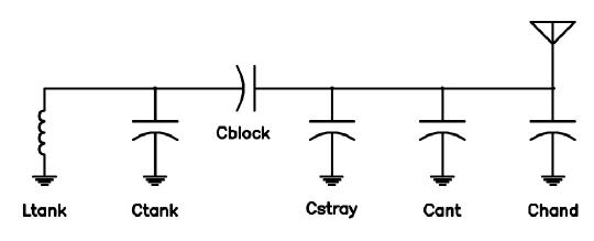
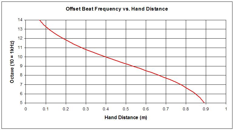
Analog Theremins generally get their "voice" from the heterodyning process (non-linearly mixing two high frequencies together and taking the difference frequency).  The modification of pitch sensitivity and linearization in an analog Theremin is usually implemented via a parallel tank / series EQ coil construct, a configuration that dates back to the earliest Theremins, and was also a favorite of Bob Moog.  The volume side of things is usually an oscillator feeding a bandpass filter, the rectified output of which is used to control a VCA.


GOALS
1. The main goal of this thread is to come up with at least one complete (pitch and volume) analog Theremin circuit that:
- is simple
- is inexpensive
- is stable
- is tolerant of active component substitutions and passive value changes
- uses components that will be readily obtainable for the foreseeable future
- is easy to setup, tune, and maintain
- is sufficiently low voltage and low current to enable battery powering
- has sufficient voltage swing at the antennae

2. A secondary goal of this thread is to lay down some theoretical groundwork in common engineering terms.  This is NOT to yack the ears off of passerby and drown them in tens of pages of thread, nor an attempt to destroy the inherent beauty and mystery of the Theremin, but to grasp what is going on in the most concrete way possible, to further our understanding of it, and to enable meaningful communication between developers and experimenters.

3. NOT goals of this thread:
- to produce an improved Theremin
- to push the state of the art in analog Theremin design


IMPLICATIONS
To meet the goals, I intend to go the simplest and most direct route possible.  This immediately rules out:
- the parallel tank & EQ inductor configuration, which IMO is difficult to tune and maintain
- exotic coils like IF transformers, low self-capacitance scramble wound RF chokes, etc.
- expensive multi-plate panel mount variable capacitors
- OTA op-amps, 2/4 quadrant multiplier/mixer ICs, etc.
- photoelectric means of controlling the volume envelope

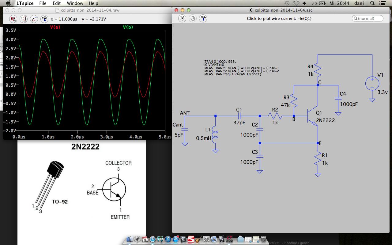
All generic R and C fixed value passives are fine.  Inductive passives should be untapped enclosed ferrite chokes or single layer air core.  For actives, I think JFETs are probably OK, but generic bipolar transistors (2N2222, 2N3904, 2N3906, etc.) are preferred from an availability standpoint.  CMOS gates are borderline (but some kind of circuit employing them might be fun to include).  Generic opamps are borderline from a supply current, I/O swing perspective.  Linear regulators are fine.

It's not like the old days when transistors were uber expensive.  So the use of extra transistors for buffering and such shouldn't be discouraged if they suppress undesired interactions in the circuit and don't add too much to the overall complexity.

I understand oscillators from the digital side of things so that's where I'll start.  My knowledge of analog mixing and volume control is less fleshed out, so I'm sure I'll pull a boner now and then and would highly appreciate any advice in those directions.

Posted: 11/4/2014 10:12:02 PM
dewster

From: Northern NJ, USA

Joined: 2/17/2012

LC Heterodyned Octave Range Invariance

A rather startling (to me) principle I stumbled across lately is this: 

1. If you have a simple LC oscillator (one inductor, series or parallel tank) with the capacitor exposed to the environment via a standard rod "antenna".

2. If the output of this oscillator is beating against that of a second, fixed oscillator, so that the difference frequency is zero when your hand is some fixed distance away (at the "null point").

3. Then, no matter what you do to the value of the L, and no matter how you capacitively pad or place capacitors in series with things, as long as the two oscillators are properly nulled you will get the same number of playable octaves (difference frequency) from the arrangement.

In altering L and/or C the bulk location of the playing span will likely be higher or lower, but the number of octaves will be the same.

So we seem to be stuck with a certain number of octaves - a certain sensitivity if you will - by using a simple LC as our capacitive sensing oscillator.  Where should this span be placed?  Human hearing is roughly 35Hz to 16kHz.  The geometric mean of this is 715Hz.  So, as a very rough first goal, positioning the hand around the midpoint of the playable pitch zone should produce somewhere in the neighborhood of this pitch.

This can be easily checked if one has a single candidate LC oscillator setup on one's bench by using a frequency counter.  Note the frequency with the hand perhaps ~0.8 meter away, then note the frequency with the hand located at 1/2 this distance.  To meet the above first goal the difference should be around 700Hz.

Here is a picture of the theoretical pitch response of an LC oscillator set up to do this:

On the Y axis of the graph the value 10 corresponds to ~1kHz, so the limits 5 and 14 here correspond to ~31Hz and ~16kHz respectively, or roughly the human hearing range.  The straightest portions of the line represent the most linear playing regions in the pitch space.

There are definitely reasons to alter this response one way or the other, primarily to make playing in the upper or lower registers more linear and therefore easier.

Spreadsheet is here: http://www.mediafire.com/download/cp1ead5xa2h7rdm/Analog_Digital_2014-10-30b.xls

Posted: 11/4/2014 10:49:53 PM
dewster

From: Northern NJ, USA

Joined: 2/17/2012

Candidate Oscillator

I've been simulating and benching oscillators lately, and this one seems rather nice from a goals standpoint for this thread:

It is a bipolar variant of livio's Theremino Colpitts using a self biased NPN instead of a FET.  I picked this tank because any self capacitance of the coil will likely be swamped by the external capacitance C1 "seen" by the coil.  The large capacitances C2, C3, and C4 lower the impedance levels thus making it more amenable to the use of an NPN, and the capacitive imbalance between C2,C3 and C1 form a split capacitor that jacks up the antenna voltage swing.  It oscillates fine on the bench with an air core coil for L1, measured antenna voltage is ~50V p-p, operating point is ~940kHz, and current draw somewhere around 1mA.  R2 smooths things out a bit and protects the B-E junction (particularly in the presence of ESD, but I haven't tested this at all).  This is a parallel tank, so I wouldn't recommend putting a series EQ inductor on it unless you really know what you are doing.

Simulation is rather different from what I'm actually seeing, voltage swings on the bench are lower, with the base swing staying above ground.

LTSpice is here: http://www.mediafire.com/download/g8d3pq5accip5kt/colpitts_npn_2014-11-04.asc

Posted: 11/5/2014 12:04:03 AM
dewster

From: Northern NJ, USA

Joined: 2/17/2012

Exotic Oscillators & Magic Antennas

I'm going to run counter to some thought here by stating my belief that there are no "special" oscillators out there with magical properties.  Oh sure, you can stick an EQ coil on a parallel tank and generate all kinds of headaches (along with some tunings that perhaps increase in linearity and/or reduce sensitivity) but in terms of single L oscillators they will all behave the same from a frequency deviation standpoint.  Lambda diodes, push-pull drive, negative resistance, quadrature sensing, split tanks, etc. - they're all the same in the pitch response department.  Some may play nicer with FETs or tubes or certain coils, or give you nice things like high voltage swing or better absolute sensitivity (deltaF/deltaC) and the like, but that's it.

Similarly, there is not a lot of difference in pitch response based on antenna geometry.  Make it 250mm long, 500mm long, it's going to have a little more or less capacitance, but it's pretty much going to do the same thing, and any linearity/nonlinearity will still be pretty much the same.  Make it a spring and the capacitance will change a little when you stretch it.  In terms of absolute sensitivity the best antenna geometry is probably a small plate or "petal" shape (livio pointed this out, and I've since done some rudimentary theoretical capacitive analysis of plates) but most players are used to playing a rod, which is probably more linear, so here we are.

I state the above not to upset or inflame others, but to spare beginners years of barking up fruitless trees.  Anyone finds an effect to the contrary, I'd be happy to listen, but be prepared to describe it in terms that I can understand.

Posted: 11/5/2014 5:07:59 AM
xtheremin8

From: züriCH

Joined: 3/15/2014

dewster, firstly thanks for starting it. 

very good definitions of the goals. it's like a back to basics. i'll would like to follow this project, like one who is complete new to the materia, also to achieve a deeper understanding of simulation and construction of circuits. but as a newt, a not entirely wrong t(h)inker, one get's quite confused when it comes to math/physics and the basic electronics. and the reading of electronic books is mostly dry as the sahara. and not one ended up in a theremin.

as a first Spice user, never did before, and it's not... the dreamer has awakened.(ohdear),  new to mac, i think i'll have to download the mac version, to follow through here. but to have a go,  i tried a ipad version called multisim touch and spiced the oscillator above, very easy to do. like lego, a bit. i placed probes in the simulation on almost all possible points, to measure voltages over a period of time . pressed start, and it seems to work. all probes show voltage etc. and on a diagram one can see how a wave starts to grow to a certain level. didn't dig deeper,  but for a complete noob i need to know where is the oscillator output, probing point. and what should be expected? a pb mark on further schematic would clear out all my questions, i learn more by doing.but i see, my learning curve is steep.

so i try to keep my saucy nonsense by myself ;-) but hard trying to keep on tracks.... dewster, you mentioned the use of plate antenna, so why not use this for the volume side? it's already aproved by them masters too. technically and artistically.


Posted: 11/5/2014 3:43:06 PM
RoyP

From: Scotland

Joined: 9/27/2012

dewster, thanks for generating this thread.
For me it is really interesting to see what thinking there is behind all of the stages required for a working theremin.
Afraid though that unless it is really a very simple problem then I’m not going to be able to have much of a positive input into this project as my level of electronic knowledge is low-albeit significantly more increased since I started looking into theremins.
Would it be fair to say that one would end up with a variant of the Melodia or Kustom design given that these seem to be pretty basic?
These seem to be pretty accessible constructions for beginners except the custom wound inductors.
Another thought, or maybe the same one put in a different way: given the aims of the qualities of this theremin, starting from a ground up approach, is it likely that what you’d end up with is something pretty similar to the Melodia or Kustom?

Posted: 11/5/2014 4:19:05 PM
dewster

From: Northern NJ, USA

Joined: 2/17/2012

xtheremin8: I'm not sure if there are proprietary things going on with the LTSpice schematic files but I wouldn't be surprised (PSpice in general uses a text based node and element list).  Were you able to open the LTSpice schematic in multisim touch, or did you have to recreate it?  LTSpice is kind of clunky until you get used to it, kind of reminds me of DOS or Win3.1 stuff.  But, like everything I suppose, once you use it enough it becomes second nature (and it is free).

Output from the oscillator could be at the base or emitter of the transistor, or even the collector if C4 is reduced and you want something radically less sine shaped.  I haven't decided this yet.

I should have been clearer re. the plate antenna.  I was talking about the pitch side and not the volume side so much.  Here are a couple of pix that livio posted a while back on the digital thread:

The top photo shows the petal antenna for the pitch side.  The photo unfortunately crops off the top, it looks something like an elongated ping-pong paddle.

RoyP: Yes, my aim is to end up with something similar to the Melodia, but easier to build and maintain.  A first DIY Theremin that isn't trivial nor overly complex.  I'm not 100% sure what the final circuit will look like, but 4 to 8 transistors seems likely.  I have zero mixer knowledge and zero VCA knowledge so it is going to take a while, hopefully on the order of months and not years. (<= scared everyone off ;-)

Posted: 11/5/2014 11:09:48 PM
xtheremin8

From: züriCH

Joined: 3/15/2014

@kustumMelodia: seems like your circuitry might get a bit deeper examined, hope you don't mind.

RoyP wrote: For me it is really interesting to see what thinking there is behind all of the stages required for a working theremin. Afraid though that unless it is really a very simple problem then I’m not going to be able to have much of a positive input into this project as my level of electronic knowledge is low-albeit significantly more increased since I started looking into theremins.

 i share that, if i may.  that's a bit the crux about kit building: one get's some skills, mostly soldering, without really the basic electronic knowledge; finally a working device. so i hope i can at least learn something new, by following (mostly) silently through. to do so, i need to figure out some things.:

@dewster: as to be expected: the multisim is just the gateway drug for Spice.But a good one. I had to recreate the schematic. that's the fun part. Ipads are just rigid on importing file formats, or damn complicated to do so sometimes. anyway, LTSpice on mac works. just had to delete the .txt extension (added by my mac i guess) and imported it as i figured out, how it should be done. my third hand is always on the help-button, and the entire english language...but so far it looks like this:

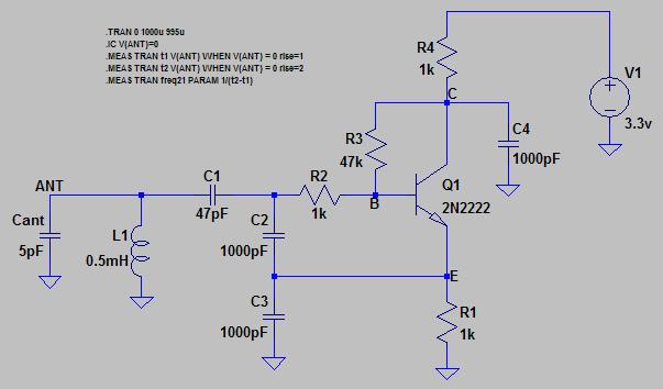
the c b e points in your schematic does make sense. stupid me.
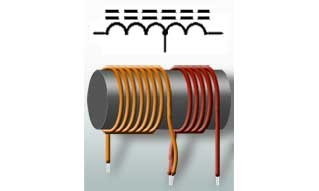
 seems it works.?  there are two different cursors showing up,(ah forgot to get them on the screenshot) one says: click to plot voltage,looks like a multimeter-tip; the other: click to plot device current, or: click to plot current into pin, looks like a ocular to me. my question: what is the difference, wich one to use? i'll try to figure out some more on my own, as much as i can. the software looks quite well documented. and i don't want to be a pain in the lower back so:

@all: any links on further reading are more than welcome, i might put them finally altogether into my first post above, to keep tings a bit tidy. 

for someone new like me ,we have the expression: to be wet behind the ears. and i'm dripping.

from the screenshot: there seems to be no toolbar <8-o  (i miss my old win-machine sometimes)


@theremino, sad the pictured paddelantenna is chopped. but one can imagine how it looks. the italians have still a distinctive sense for design. no doubt.

it looks to me like such a plate pitch antenna would have a more bidirectional field, like a traditional volume loop antenna has? (a rod antenna field "looks" more like candy-cotton to me.) it seems  unusual and new, but if i'm correct about the field, it has something to be said for it. funny bunny ears, reminds me on my previous avatar.

Posted: 11/6/2014 3:53:05 AM
dewster

From: Northern NJ, USA

Joined: 2/17/2012

xtheremin8: Those waves look good, seems you've got it working fine at approximately 1MHz, with the base swing ~2x larger than the emitter swing (as one would expect from the capacitive voltage divider C2 & C3). 

Voltage is like water pressure, you can measure it at a point (it is actually differential and usually referenced to ground). Current is like water flow, you have to measure it as it flows through a conductor.  (The "ocular" icon is that of a current probe, which is a magnetic loop placed around a conductor to sense the current flow through it via the magnetic field produced by the current.)

NPN and PNP transistors work like current valves, the current that flows from the base to the emitter is amplified by the transistor beta (an ill-specified parameter, common values are in the range 50 to 200) and results in a larger current flowing from the collector to the emitter.  Because of this resistors on the emitter side are seen by the base side as multiplied by the beta.  So here the 1k of R1 looks like ~100k to the base, unloading things on the base side.  This isn't the best circuit to learn the rudiments on as there is a lot going on.

Missing toolbars, I feel your pain.  They take them away and give us ribbons, or more often nothing, and you're frantically right clicking on gears or empty spaces where they used to be.  They're still there generally, just hidden for no real reason but the fickle whims of evil software UI developers.

A pitch plate would be more sensitive and bidirectional, but ironically might actually be more linear played on the side rather than straight on.

Anyway, now that you've got Spice and a circuit, try probing different spots, changing values, playing around to see what changes what - I usually change things by multiples of 2 (1000pF => 2000pF; 47pf => 22pF; etc. common resistor, capacitor, and inductor component values are multiples of 1, 2.2, 3.3, 4.7, 6.8, 10, 22, etc. ).  Look at the antenna voltage swing, it should be quite a bit larger than any other voltage swings in the circuit.  Look at the current through the collector resistor R4, this is the current draw for the oscillator and should be a sawtooth wave with ~1.2mA average.

Posted: 11/6/2014 1:50:19 PM
xtheremin8

From: züriCH

Joined: 3/15/2014

voltage and current swing on multisim just to visualize what dewster wrote above. had to stretch it a bit to show the higher antenna voltage. thus, the Vb and Ve look a bit different, if i'm correct.  btw, the computer-software costs thousandsomehundreds. the pad version 1 sfr.?! I also spotted once another mac spice freeware. maybe with a toolbar;-)   Anyway, you hooked me on spice dewster. thanks for that so far, i have work for days now, maybe weeks ahead with all that, beside what life commands. i saw so many different schematics of oscllators mixers filters,etc....i know it's not the real world, nor a alternative for breadboard. but usefull for trying circuits without burning the half house down...frankly, i feel a bit like Leeloo , learning it the 5th element way . hardcore. so it will take me some time to let it settle a bit and to become a bitmore handy with it.  it takes me quite some time to put my humble english somehow together anyway.

apropos hooked: are the wound coils, variable conductores out of question? i have no solution on how the ones in the melodia, these 4 scary looking ones, mounted on the chassis, could be replaced. as to be seen in the melodia foto album. after rerreading some threads i thought it might be not that difficult to create some handknitted ones. but i leave this up to others, to decide.

@dewster, you realy do a fine teacher.

You must be logged in to post a reply. Please log in or register for a new account.