Let's Design and Build a (simple) Analog Theremin!

Posted: 11/13/2014 12:39:32 PM
dewster

From: Northern NJ, USA

Joined: 2/17/2012

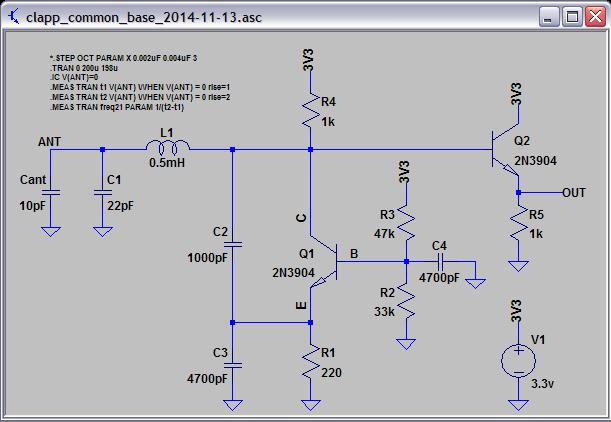
Here is a somewhat better oscillator candidate:


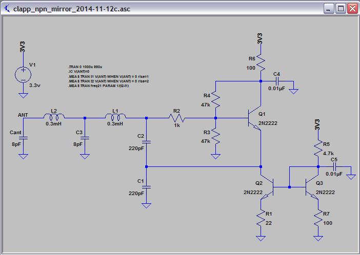
It's a Clapp, with the Q1 emitter sourced from a current mirror.  This unloads Q1 and makes the impedance seen by the tank at the base of Q1 somewhat higher impedance, allowing higher voltage swings.  The bench circuit behaves somewhat differently than the sim, with voltage swing safely within VCC/GND at the Q1 base.  Unless you grab the antenna, at which point the voltage increases to a bit higher than the supply rails (given my breadboard setup anyway).

I believe I've seen a large improvement using counter-wound air coils for L1 | L2 (i.e. reception / reduction of magnetic field interference).  The center tapped capacitor C3 helps oscillation but probably doesn't improve SNR.

(I've been trying to find a BJT based oscillator that works as good as a FET based one, the above is as close as I've been able to come so far, but the FET is still somewhat better from an interference / phase noise standpoint.  FET Clapp + NPN emitter follower is simply amazing.  The above is about as stable as the FET, and would likely be fine for use in this thread.)

LTSpice: http://www.mediafire.com/download/14oj5eccobeywb4/clapp_npn_mirror_2014-11-12c.asc

Posted: 11/13/2014 3:50:32 PM
xtheremin8

From: züriCH

Joined: 3/15/2014

rebuilt it and swings also fine on my ipad. but uses so much memory, it stops simulating after about 100 mycro-seconds. ah,the technical limits. lol. so just to make sure what i see: it oscillates at about 2mhz? and this will be the var.osc.? thanks for the spice files. appreciate it very much. 

Posted: 11/13/2014 4:23:09 PM
Alesandro

From: Russia, The city of three revolutions

Joined: 4/20/2013

Dewster,

how the frequency of the oscillator was selected?..

Do the counter-wound air coils have more self-capacitance then two simple single-layer coil???

Posted: 11/13/2014 10:22:59 PM
dewster

From: Northern NJ, USA

Joined: 2/17/2012

"so just to make sure what i see: it oscillates at about 2mhz? and this will be the var.osc.?"  - xtheremin8

About 2MHz is right, and yes this would be the variable oscillator with the antenna and all.

"how the frequency of the oscillator was selected?..

Do the counter-wound air coils have more self-capacitance then two simple single-layer coil???"  - Alesandro

The frequency will likely be in the 1 to 2MHz range, and this was picked by using the spreadsheet on the first page of this post and a bit of hand waving (a better estimate is TBD).

Counter-wound air coils have the same self capacitance as two air core coils spaced far enough away from each other on the same former so as to have negligible mutual magnetic coupling.  I don't know if it will have much bearing on this project, I brought it up more to note it.  The counter-wound coil I'm currently using is two windings of 0.3mH spaced 18mm apart on a 27mm diameter former (PVC Schedule 40 0.75") using 34AWG (single coat insulation).  Each winding is ~20mm high (this is ~10 meters of wire for each winding).  But that's just what I had laying around.

Posted: 11/14/2014 5:34:17 AM
Alesandro

From: Russia, The city of three revolutions

Joined: 4/20/2013

Thanks Dewster, but, in the matter, the question is: Do you take into the account some issues (if it needed???...) about:

oscillator stability;

radio interference;

the coil size;

and ....??? more ???

then the frequency of the oscillator was selected?..

Posted: 11/14/2014 12:22:47 PM
dewster

From: Northern NJ, USA

Joined: 2/17/2012

"Do you take into the account some issues..."  Alesandro

Stability - thermal, flutter, phase noise, etc. - is dictated by oscillator topology and the components used. 

Mains hum pickup can be via both electric field and magnetic field - outside of counter-winding inductors or concentrating the magnetic field with ferrite there isn't much you can do about the magnetic component.  I think series capacitances don't do much if anything to reduce the electric component (though they could help in other ways).

Coil size probably won't be that important.  Hoping to keep things around or above 1MHz where even hand wound air cores are pretty small.  Will most likely use IFTs for tunability, and they are quite small.

Radio interference is an interesting point.  For my digital Theremin I'll probably take livio's advice and stay between 2MHz and 3MHz.  For this project the operating point will be dictated more by the heterodyned output frequency, which may put it smack dab in the middle of the AM band.  Large antenna voltage swing may make radio interference rather moot (at least for the Theremin).

"but uses so much memory, it stops simulating after about 100 mycro-seconds."  - xtheremin8

Try reducing the transient statement.  I've got it set up to record way out in time to let bias settle down and to let oscillations build up.

.TRAN 0 50u 48u

Another trick in there is .IC V(ANT)=0 which gives the tank a kick in the pants.

Posted: 11/14/2014 2:20:48 PM
dewster

From: Northern NJ, USA

Joined: 2/17/2012

Got this beauty running (~1.2MHz) on the bench last night and optimized it some this morning:

It's a common base Clapp and it's kind of hard to imagine how the heck it even works.  Normally you sense the thing you want to amplify with the base input, but in this case the base is more or less anchored to a fixed voltage, and when the emitter swings low enough to turn on the BE junction (Vbe = 0.7V or a diode drop) you get CE conduction.   C3 "sees" the fairly low value emitter resistor R1, and the base impedance divided by beta and as well, so we have to size up C3 quite a bit and watch the base impedance.  The parallel combination of R2||R3 divided by beta is on the order of R1, and C4 is on the order of C3.  C2 is large compared to the antenna and tank capacitance which gives us a healthy voltage swing (I measure ~30V p-p on the bench). 

PROS:

  • With the above base bias and impedance (optimized for a 2N3904) there is amazingly little variation in frequency with large supply voltage variation (2.5V to 3.3V) - this circuit could likely get by without a regulator (though you always want to use one for the added stability).  This helps to reduce interaction between multiple oscillators being fed by the same voltage source.
  • The output buffer Q2 conducts out of phase with Q1, so the net current draw is an almost constant 1.2mA 3mA - pretty neat!  This also helps to reduce multiple oscillator interaction.
  • It is self-starting, and doesn't stall when I touch the antenna (though my antenna is insulated with heat-shrink tubing). 
  • Phase noise seems quite low (on par with FET Clapp) and there isn't much fluttering on the scope or long settling time after a cold power-up (also on par with FET Clapp). 

CONS:

  • The lower impedances of this circuit tend to load down the tank, giving lower Q and lower voltage swing, which could increase unwanted interaction with environmental noise and other oscillators nearby. 
  • It's a bit picky when it comes to component values and transistor characteristics compared to other topologies (optimal bias  for 2N2222A vs 2N3904 is a somewhat different).
  • Explicit tank capacitance C1 is required for oscillation.

Gotta see if it plays nice with other coils, but it's probably a keeper.  If it weren't for C1 I'd be tempted to use it in my digital Theremin project (where maximum absolute sensitivity is needed), but for this project it seems almost ideal.

LTSpice: http://www.mediafire.com/download/xdqw47kvsx1j14n/clapp_common_base_2014-11-13.asc

[EDIT] In simulation it stops oscillating with inductances above ~4mH, and the voltage swing is strongly correlated to the inductance value, which is kind of weird, but it seems pretty happy with large capacitance values.  For this project the inductance will almost certainly be below 1mH.

Posted: 11/14/2014 6:38:53 PM
Alesandro

From: Russia, The city of three revolutions

Joined: 4/20/2013

But why so many ocsillators?.. I think you have one(in the beginning), or two  schematics ideal for beginners and dreamed to present it to my friends, who wants something simple and reliable...


Posted: 11/15/2014 1:26:02 AM
dewster

From: Northern NJ, USA

Joined: 2/17/2012

"But why so many ocsillators?"  - Alesandro

Because the better is the enemy of the good?  ;-)  Buckle up, we haven't gotten to the 100 versions of the mixer yet!  (I hope I keed.)

Anyway, some finessing of the last one:

The main difference is the base of Q1 is now dynamically self-biased by the collector, which makes it more amenable to transistor and tank (inductor and capacitor) variation.  Also the value of C1 is doubled.  Output on the bench is a nice looking 1.9V p-p almost-sine (simulation shows a higher amplitude with the bottom chopped off).  Simulation shows oscillation with larger L by increasing C2 to the value of C1, haven't physically checked that.  Anyway, it's been running all day on the bench and looks pretty nice.  This common base stuff is like alien technology - Theremin research can really flesh out your technical background.  And those early radio guys really knew what they were doing!

LTSpice: http://www.mediafire.com/download/y63rib83c433jlp/clapp_common_base_2014-11-14.asc

Posted: 11/15/2014 9:58:14 AM
Alesandro

From: Russia, The city of three revolutions

Joined: 4/20/2013

...so, is it better then osc with the "current mirror"?..

...and what's about linearity and sensitivity issues?..

You must be logged in to post a reply. Please log in or register for a new account.