Let's Design and Build a (simple) Analog Theremin!

Posted: 11/24/2014 9:58:58 PM
FredM

From: Eastleigh, Hampshire, U.K. ................................... Fred Mundell. ................................... Electronics Engineer. (Primarily Analogue) .. CV Synths 1974-1980 .. Theremin developer 2007 to present .. soon to be Developing / Trading as WaveCrafter.com . ...................................

Joined: 12/7/2007

"Fred, you are right - more frequency, more sensitivity!.." - Alesandro

Not sure I am "right".. If one expresses "sensitivity" in terms of percentage change in frequency, then I think there is probably little / no difference.

But  difference frequency between two oscillators in actual terms (as in Hz rather than %) there is a direct relationship which increases as frequency increases.. 1% of 100kHz = 1kHz, 1% of 1MHz = 10kHz.

As I see it, in terms of "sensitivity" (and for that matter, stability etc) similar oscillators running at 100kHz / 1MHz will probably perform equally, and the higher frequency oscillator will be "better" because it requires smaller inductor/s..

BUT.. For a direct-to-audio heterodyning theremin, as I see it, one needs to reduce the difference frequency down to the audio range, and this is the only issue I have a problem with.. There are possibly ways to implement this and implement linearization in so doing (make the reference oscillator a VCO and vary this as a function of the variable oscillator frequency for example) but this is (to me anyway) far from "simple".

One could also divide down the VFO with logic and mix this with a lower frequency reference oscillator.. But apart from this the only simple solution I can see is to make the antenna itself extremely low capacitance (long really thin wire?) so that the variable (hand) capacitance change is reduced to perhaps 0.2pF.   This may go some way to improving linearity as well, would be real simple, but I would be worried about drift ..

I have a strong feeling though that I am missing something - I dont get the "invariant" aspect of this, or at least I dont get it when it comes to producing audio. So I will simply follow this thread in the hope that it all becomes clear ;-)

Fred.

Posted: 11/25/2014 12:14:40 AM
RoyP

From: Scotland

Joined: 9/27/2012

I have a strong feeling though that I am missing something - I dont get the "invariant" aspect of this, or at least I dont get it when it comes to producing audio. So I will simply follow this thread in the hope that it all becomes clear ;-) - Fred


Aye, me too...

That said, it's great to get an insight into the design from bottom up, as it were, thanks dewster et al.

R

Posted: 11/25/2014 8:02:08 PM
dewster

From: Northern NJ, USA

Joined: 2/17/2012

Fred, I agree with everything you've written.

I've had a bit more time to think about the invariant, and believe I understand what is going on in simpler terms. 

1. If one quadruples the value of L then the oscillator frequency drops by one octave, and the heterodyned Theremin pitch response also drops by one octave (i.e. the Theremin is transposed down 1 octave).  Agreed?

2. If one quadruples the value of C then the the oscillator frequency drops by one octave, but the heterodyned Theremin pitch response drops by three octaves (i.e. the Theremin is transposed down 3 octaves).  As in the L case, one octave of drop is caused by the oscillator frequency dropping an octave.  But the other two octaves of drop are caused by a "double doubling" of the capacitive padding, causing a 4x drop in absolute sensitivity.  So there are two mechanisms that lower heterodyned pitch when increasing the capacitance: the first in a square root sense due to the lowering of the oscillator absolute frequency, the second in a direct sense due to the lowering of absolute sensitivity.

By the above reasoning, we can construct Theremin oscillators that operate at different absolute frequencies, but produce the same heterodyned result.  Whatever we scale the capacitance by, call it x, we must then scale the inductor by (1/x)^3. Or equivalently, scaling the inductance by y means we must then scale the capacitance by (1/y)^(1/3).

Pulling numbers out of the air, say the schematic for a certain Theremin employs 315kHz oscillators and calls for L=16mH and C=16pF.  We look in our junk box and can only find a 1mH inductor.  So we scale C: 16pF*[1/[(1mH/16mH)]^(1/3)=40.3pF and our oscillator now runs at 793kHz but gives us the same heterodyned result.

Since the capacitive padding changes relatively little with oscillator frequency, we see designs out there that run at anywhere from <200kHz to >1MHz.  There are obviously limits to the above beyond which things start getting outrageous.  Higher frequencies are nice because they use smaller inductors and filtering out the unwanted additive products post mixing is easier.  Lower frequencies are nice because oscillator stability is less of an issue.

The static or free-space capacitance of the pitch antenna is on the order of 5-10pF, and this along with any other stray capacitance fixes the lower limit at which any Theremin can operate in an equivalent manner to higher frequency designs.  (When I say "equivalent" here I mean the ability to null at the same point, and then produce the same heterodyned frequencies at the same points within the pitch field, as another design.)

The invariant means you will always get this kind of linearity no matter what you do or how many capacitors you throw at it or where you put them, and as long as it is properly nulled and sufficiently decoupled:

Another way of looking at things: altering absolute sensitivity transposes the Theremin, but has no impact on heterodyned sensitivity nor linearity.  This is constraining but also quite freeing.  We can pick the oscillator frequency for various engineering reasons and with the expectation that we will be able to transpose the Theremin to where we want it via capacitive padding.

Posted: 11/26/2014 4:39:24 PM
FredM

From: Eastleigh, Hampshire, U.K. ................................... Fred Mundell. ................................... Electronics Engineer. (Primarily Analogue) .. CV Synths 1974-1980 .. Theremin developer 2007 to present .. soon to be Developing / Trading as WaveCrafter.com . ...................................

Joined: 12/7/2007

"Pulling numbers out of the air, say the schematic for a certain Theremin employs 315kHz oscillators and calls for L=16mH and C=16pF.  We look in our junk box and can only find a 1mH inductor.  So we scale C: 16pF*[1/[(1mH/16mH)^(1/3)]]=40.3pF and our oscillator now runs at 793kHz but gives us the same heterodyned result." - Dewster

Ok! - I see what you are saying here (at last ;-) Provided one keeps the ratios of L==C as you detail above, the oscillator sensitivity (Hz/pF) will be the same (regardless of actual frequency), and the "invariant" will apply.

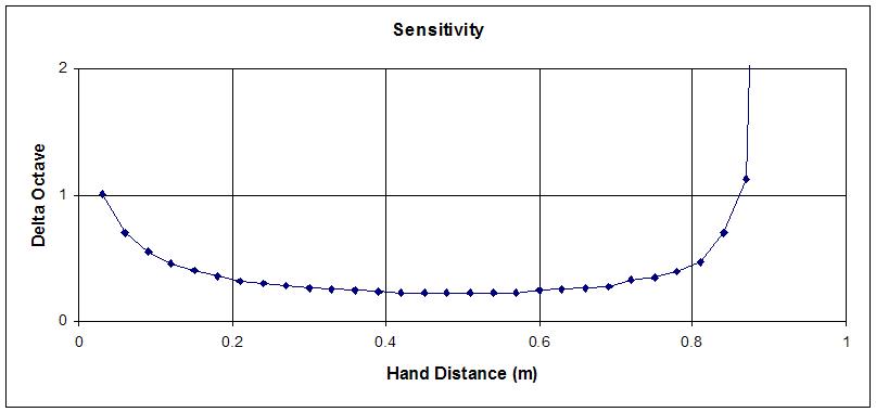
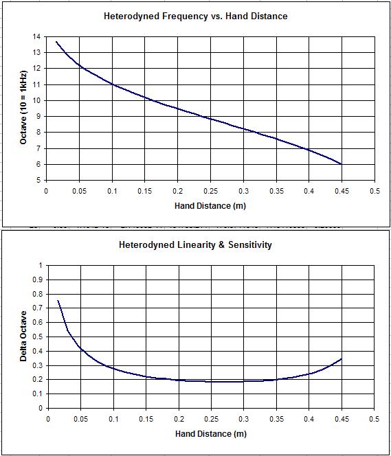
In the above example, the selected components (both for the 315kHz and 793kHz versions) give sensitivity to capacitance change of about 9.5kHz/pF. For the sake of argument, lets assume the C-Hand variation over the playing field is 1pF, then after heterodyning one gets (16Hz to 9.5kHz) 9 octaves.

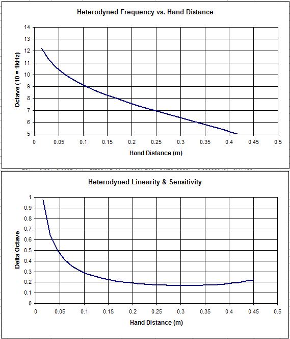
If one increases the 1mH/40pF oscillator capacitance to 100pF, it runs @ ~500kHz with a sensitivity to capacitance change of about 2.5kHz/pF, and after heterodyning one gets (16Hz to 2.5kHz) 7 octaves, and the same would apply if one altered the oscillator frequency making changes to LC in the manner you describe above.

But I still do not get your "Another way of looking at things: altering absolute sensitivity transposes the Theremin, but has no impact on heterodyned sensitivity nor linearity. " - As I see it, 1mH;40pF gives me 9 octaves, 1mH;100pF gives 7 octaves (for a 1pF change and heterodyning with an oscillator running at the highest VFO frequency).. As in, I dont see that one can do capacitance "padding" to "transpose" the frequency without such "padding" altering the sensitivity, and AFAICS one can (with padding) set whatever "sensitivity" (post heterodyning, # octaves) one wants within the playing zone - but the more one packs in, the more non-linear and difficult it will be to play any of them!

I think there may be a problem with the terms "transposition" and "sensitivity" - In essence, I think what you are saying is perhaps "correct" - reducing sensitivity can be seen as "transposition" in that halving sensitivity will reduce the 'span' by one octave and therefore 'transpose' the heterodyned output by one octave.. But as there is an arbitrary lower audio limit (16Hz) to me this is more a sensitivity than a transpose function - transpose would, to me, result in (for example) the 16Hz "location" producing 32Hz, and all other "locations" changing proportionally.

I thought I could see your plan before you presented a mixer directly connected to your oscillators - I was expecting your (superb) high frequency / high sensitivity "antenna" oscillator to drive something like a 4040 to drop its frequency and reduce effective sensitivity prior to mixing with a lower frequency reference, and was even thinking that perhaps you were leading up to a simple register switching implementation - but I am kind of at a loss now... I dont know if you can 'pad' your oscillators sufficiently to reduce their sensitivity without this impacting on the antenna voltage... The idea of high frequency low power oscillators is lovely, and I hope you can pull it off!

fred.

Added ->

I have actually got myself a little confused after writing the above.. The whole "transposition" vs "sensitivity" issue... As I understand the EWP operation, "register" selection is done by dividing both reference and VFO frequencies, prior to heterodyning.. So a location producing say 64Hz will produce 32Hz if the lower octave is selected, and 128Hz if a higher octave is selected.... In this sense though, both transposition and sensitivity change do equate to the same result... ?

But enough! - I really need to stop reading these posts..

Posted: 11/30/2014 2:52:48 PM
dewster

From: Northern NJ, USA

Joined: 2/17/2012

"I think there may be a problem with the terms "transposition" and "sensitivity" - In essence, I think what you are saying is perhaps "correct" - reducing sensitivity can be seen as "transposition" in that halving sensitivity will reduce the 'span' by one octave and therefore 'transpose' the heterodyned output by one octave.. But as there is an arbitrary lower audio limit (16Hz) to me this is more a sensitivity than a transpose function - transpose would, to me, result in (for example) the 16Hz "location" producing 32Hz, and all other "locations" changing proportionally."  - FredM

If you remove the arbitrary lower limit (i.e. assume the ear can hear subsonic and supersonic notes) then I believe we're in agreement.  As long as it is re-nulled, altering L and/or C will cause the notes at all fixed locations to change proportionally, and the number of octaves in the playing field will always be the same (even if we can't hear them).

"As I understand the EWP operation, "register" selection is done by dividing both reference and VFO frequencies, prior to heterodyning.. So a location producing say 64Hz will produce 32Hz if the lower octave is selected, and 128Hz if a higher octave is selected.... In this sense though, both transposition and sensitivity change do equate to the same result... ?"

Yes, exactly.  Transposition via digital frequency division is an excellent illustrative comparison!  (And an excellent way to employ higher frequency oscillators with smaller coils - though I wasn't thinking along those lines and perhaps I should be).  Dividing both reference and VFO by the same number preserves the null point and is quite clean.  Altering things via L and/or C requires a renulling, but otherwise the effect can be made equivalent.  (The basic curve of the hand capacitance is what produces the invariance.  There is only ~30 femto-Farad increase going from far field to mid field, so even the antenna free-space capacitance dwarfs it.)

Posted: 11/30/2014 5:23:44 PM
Thierry

From: Colmar, France

Joined: 12/31/2007

Just some info about some existing theremin models without linearization coils, which could help in your respective thinkings...

The tVox tour has simple LC NDR oscillators without whatever frequency division. It has a relatively thick pitch antenna which is installed a few cm above the metal ground plate of the housing, so that the static antenna capacitance is 10pF. It is internally in parallel with another 10pF capacitor. Since the coil inductance is 65mH and the operating frequency 135kHz, there must be a parasitic capacitance of 2pF, so that the over all free-run capacitance is about 22pF to which you would have to add 1.5pF to play C8 (4186Hz) which is easy on that instrument, since the antenna is thick. I can obtain that tone with my hand fully extended, which means Carolina's playing position #8 where the antenna sees mainly and only three fingertips, at 1cm from the antenna. But this antenna thickness makes also (that has most probably to do with the density of the field lines) that the tone-spacing is very small in the highest register which can partially be compensated by approaching your whole body.

Then, there is the Henk prototype theremin where the VPO is a Clapp-Gourriet oscillator with an inductance of 50mH running at 150kHz. The over all oscillator capacitance is 22.5pF to which the long and thin telescopic antenna contributes a static capacitance of 8.8pF in series with 150pF. The 3 Clapp-divider capacitors in parallel with stray capacitances add up to 14.2pF. Again, an addition of 1.5pF is needed to play C8 (4186Hz), but that is almost not working in practice. Even with a fully closed hand = big surface, you have to come very close (~5mm) to the pitch antenna (the telescopic segments at playing=shoulder height has only a diameter of 5-6mm), which makes precision playing almost impossible in the top C7 to C8 octave. But the advantage is, due to the thinner antenna (lower field line density in proximity) and the 150pF series capacitor, that the tone spacing at distances >= 1cm from the antenna is much less compressed as on the tVox.

Seen these results, I will check in the quiet time between xmas and new year if I can't improve somewhat the tone spacing of the tVox by playing with different capacitances in series with the antenna but without sacrificing the top pitch range.

Posted: 12/1/2014 2:16:18 PM
dewster

From: Northern NJ, USA

Joined: 2/17/2012

Thierry, thanks for that info!  Could you help me fill in the blanks for the Henk using the simplified schematic below (where components may not be in the correct order but the overall effect would be the same on the coil)?

tVox Tour

  • Fop = 135kHz
  • Ltank = 65mH
  • Ctank = 0
  • Cblock = infinite
  • Cstray = 12pF
  • Cant = 10pF

Henk

  • Fop = 150kHz
  • Ltank = 50mH
  • Ctank = 0
  • Cblock = 150pF
  • Cstray = ?
  • Cant = 8.8pF

If I understand you correctly, the "The 3 Clapp-divider capacitors in parallel with stray capacitances add up to 14.2pF" value is effectively in parallel with the antenna capacitance?  But 8.8pF + 14.2pF = 23pF so I'm confused.  Perhaps Cstray = 17.7pF?  That number would give an effective overall capacitance of 22.5pF (as seen by the coil).

Posted: 12/1/2014 6:00:08 PM
Thierry

From: Colmar, France

Joined: 12/31/2007

I'll publish my own commented drawings, that's easier...

First the Henk:

Henk VPO

And then the tVox:

tVox VPO

Posted: 12/1/2014 9:11:46 PM
dewster

From: Northern NJ, USA

Joined: 2/17/2012

Thanks Thierry!  (You should write a book...)

tVox Tour

This one is straightforward:

  • Fop = 135kHz
  • Ltank = 65mH
  • Ctank = 10
  • Cblock = infinite
  • Cstray = 2pF
  • Cant = 10pF

Henk

Here I combined everything to the right of the inductor in your drawing, which gives 14.18pF:

  • Fop = 150kHz
  • Ltank = 50mH
  • Ctank = 14.18pF
  • Cblock = 150pF
  • Cstray = 0
  • Cant = 8.8pF

Here are the calculated responses (spreadsheet here):

Above: tVox Tour simulation with +2pF antenna padding (over the geometrically calculated value of antenna free-space or static capacitance) to get the operating point of 135kHz, and with +50Hz null offset to improve far field linearity.  Mid-field heterodyned frequency is 502Hz.

Above: Henk simulation with +3.6pF antenna padding (over the geometrically calculated value of antenna free-space or static capacitance) to get the operating point of 150kHz, and with +20Hz null offset to improve far field linearity.  Mid-field heterodyned frequency is 133Hz.

=============

It seems to me that the tVox is a better design in terms of invariant response because the linear section of the pitch field is positioned more in the center of the range of our hearing.  The Henk is interesting in that the non-linear lower end is positioned in the subsonic region.  It's not surprising that it is difficult in practice to utilize the upper end of the Henk as it is almost 2 octaves below the tVox overall.

=============

I have serious doubts that the antenna geometry (within the 250mm to 500mm length and 5mm to 20mm diameter norms) has much to do with anything other than bulk capacitance, though I haven't done much experimenting along these lines (particularly diameter changes).  Bulk capacitance at the antenna has so much influence over the invariant point that my conjecture is that this alone tends to confuse even really bright people into thinking something more complex is going on.  But I could be wrong.

=============

That 90pF cable on the Henk looks like it could be trouble in the temperature drift department.  I think it's generally best to locate the oscillator as near the antenna as possible - it's not like it's a ton of circuitry or anything, though I suppose it is one more thing to cable and mount.  One thing the Theremini got right.

Posted: 12/1/2014 10:04:52 PM
Thierry

From: Colmar, France

Joined: 12/31/2007

They don't differ so much in real playability. Your simulations do perhaps not reflect the entire player's eality...

The c8 (4186Hz) can easily be played at 1cm of the pitch antenna on the tVox with three fingers stretched towards the antenna as I wrote above while I'll get an e7 (2637Hz) with the same hand shape at the same distance on the Henk. Thus I can't see from where you pull a two octave difference?

In practice, the Henk's overall linearity is much better than on the tVox, also in the lowest range, after meticulous pitch tuning done by slightly varying the length of the telescopic antenna.

Temperature stability is not an issue under normal conditions. The Henk's FPO is a 150kHz XTAL oscillator. At room temperature, you won't notice any drift of the VPO after a warm-up phase of ca. 5 minutes. The VPO starts only going up like hell when the instrument is on stage, heated up by spotlights.

"I have serious doubts that the antenna geometry (within the 250mm to 500mm length and 5mm to 20mm diameter norms) has much to do with anything other than bulk capacitance, though I haven't done much experimenting along these lines (particularly diameter changes).  Bulk capacitance at the antenna has so much influence over the invariant point that my conjecture is that this alone tends to confuse even really bright people into thinking something more complex is going on.  But I could be wrong."

Sorry, but you are wrong. The antenna diameter has an important impact in the near field (<= 10cm) but almost none in the far field. I didn't study your simulations to find their weak point, but I can tell you from my experience (I think that I have played, experienced, and analyzed more different Theremin models with my own hands than most people here), that it makes a huge difference. I have (as written above) this field line density theory but I couldn't yet pack it into formulae.

You must be logged in to post a reply. Please log in or register for a new account.