Let's Design and Build a (simple) Analog Theremin!

Posted: 2/19/2020 3:30:43 PM
dewster

From: Northern NJ, USA

Joined: 2/17/2012

"What I don't get is where the harmonics come from, between the mixer output and the speaker are we supposed to ensure harmonics are introduced?
Are we to introduce them prior to the mixing?"  - innominata

Harmonics are introduced via non-linearities, which can be anywhere in the signal chain.  Usually the mixer and/or after the mixer.  I've only dabbled with mixing, perhaps ILYA or Dominik could answer this better.

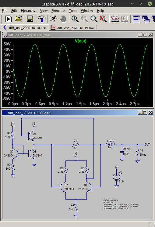
"Basically I'm trying to understand why my .wav output sound like a pure sine tone and yours sounds like a theremin."

If you see a sine wave coming from your simulation then you will probably hear a sine wave (distortion invisible to the eye can be audible).  But if your simulation is clearly producing a non-sine wave then you should be hearing harmonics.

Theremin simulations are hard to do right, as often the oscillators can take time to ramp up to their stable operating points.  You should run the sim for a long time and examine where it seems to be constant.  Also, it's really easy to mistake oscillation with LC "ringing" which just dies down, I've done this more times than I can count.

Posted: 2/19/2020 10:34:12 PM
oldtemecula

From: 60 Miles North of San Diego, CA

Joined: 10/1/2014


Out of 95,000 views did  anyone or you prove your approached worked or had value? How about a real sample, a sine wave is the foundation of all sound and I do like them if done right. It is from there we move towards a classic sound.

How harmonics are introduced you seem reluctant, a sample of that would also be nice.

Christopher

Posted: 2/19/2020 10:44:54 PM
dewster

From: Northern NJ, USA

Joined: 2/17/2012

"Out of 95,000 views did  anyone or you prove your approached worked or had value?" - oldtemecula

ILYA used one of the oscillators in a Theremin of his, which was published in a Russian magazine IIRC.

"How harmonics are introduced you seem reluctant, a sample of that would also be nice."

I don't have the time, and truthfully have only marginal interest in analog Theremins these days, so this thread languishes.

Posted: 2/20/2020 3:17:31 AM
innominata

Joined: 2/9/2020

"Theremin simulations are hard to do right, as often the oscillators can take time to ramp up to their stable operating points. You should run the sim for a long time and examine where it seems to be constant. Also, it's really easy to mistake oscillation with LC "ringing" which just dies down, I've done this more times than I can count."

I've checked and oscillations seem like they're fine from the start and continue to stay stable although slowlu dipping in terms of DC offset and then becoming stable again over time. When I try to give an initial condition to an antenna however the actual oscillations take time to begin, a long time. I'm not entirely sure what the point of giving the antenna an initial voltage is since it doesn't vary the capacitance or mimic any useful behaviour. It takes very long to simulate anything doing this. It seems easier to just manual change the antenna capacitance and see how the frequency changes without giving it an initial condition.

Am I completely wrong on this?

Posted: 2/20/2020 4:52:18 AM
dewster

From: Northern NJ, USA

Joined: 2/17/2012

"I'm not entirely sure what the point of giving the antenna an initial voltage is since it doesn't vary the capacitance or mimic any useful behaviour. It takes very long to simulate anything doing this."  - innominata

Rather like real oscillators, simulations of them rely on numeric noise to get going, and the "relaxation" calculations used to set the initial conditions before the sim starts can get in the way of this.  So providing a little "ping" somewhere can get it going faster so you don't have to wait so long for it to reach maximum swing and stability.  You often need to experiment with the initial stimulus value to somewhat optimize it, sometimes that's a really tiny value.

I've found the oscillators that tend to work better in real life don't have so many starting issues in simulation, but that's not a hard rule or anything.

Posted: 2/20/2020 7:59:48 PM
tinkeringdude

From: Germany

Joined: 8/30/2014

.Rather like real oscillators, simulations of them rely on numeric noise to get going, and the "relaxation" calculations used to set the initial conditions before the sim starts can get in the way of this.  So providing a little "ping" somewhere can get it going faster so you don't have to wait so long for it to reach maximum swing and stability.  You often need to experiment with the initial stimulus value to somewhat optimize it, sometimes that's a really tiny value.

I've found the oscillators that tend to work better in real life don't have so many starting issues in simulation, but that's not a hard rule or anything.

Interesting, could you elaborate?
What I've noticed is that some oscillators in LTspice need the "start voltage source at 0V" option to work. Since I figured, in reality, there's no such thing as everything starting at the nominal operating voltage, I wasn't too bothered by that apparent requirement.
Are those things related?

Posted: 2/20/2020 8:39:41 PM
dewster

From: Northern NJ, USA

Joined: 2/17/2012

"Interesting, could you elaborate?"  - tinkeringdude

It's just observation, perhaps over-generalized on my part - anecdata.  It really depends on the oscillator being simulated, but if I put too large an initial stimulation on it the LC might take forever to ring down, or take forever to start oscillating.  Sometimes it's like a femto-Volt or such that kicks it just right.  High Q circuits can take a long time to stabilize in simulation, and I've mistaken a bum oscillator simply ringing down for stable oscillation many, many times.  And this is with specifying gobs of time before the data collection starts.

"What I've noticed is that some oscillators in LTspice need the "start voltage source at 0V" option to work. Since I figured, in reality, there's no such thing as everything starting at the nominal operating voltage, I wasn't too bothered by that apparent requirement.

Are those things related?"

It could be the relaxation state, or DC operating point of the sim, at that node doesn't "relax" to exactly zero due to circuit topology (bias) or due to numeric rounding / truncation and such.  In that case, if you constrain the node to 0V during the relaxation calculations, once the sim starts in earnest the hounds are released by the defacto step function.

In real life there's plenty of thermal noise to stir things up, and there's always the gigantic step you get when turning the thing on (though you don't want to have to rely on that to restart oscillation should it somehow stop).

Posted: 10/20/2020 1:58:13 AM
dewster

From: Northern NJ, USA

Joined: 2/17/2012

Differential Oscillator

This is a weird one:

Differential pair Q1 & Q2 "look" at either end of resistor R1, which drives a series LC tank, so they sense the current through R1, and therefore the tank inductor, which R1 converts to a voltage.  The difference voltage drives unity buffer Q4 with constant current mirror Q3 and Q5 pulling down ~4mA.  Optimally gives ~100Vp-p at the antenna while drawing 9mA ~peak, ~5mA average from single ended 3.3V supply.  The differential pair is somewhat abused here as it operates outside its linear range.  Biasing of everything is perhaps too simplistic and dynamic?  The current mirror could be replaced with a single resistor to ground, but at the cost of increased current draw / reduced antenna voltage swing.

Works in simulation, I have no freaking clue if it works in real life or is sufficiently stable for Theremin uses.  5mA is a bit on the heavy side for pinging a high Q tank (I tend to equate current draw with heating and drift).  R1 is a Q killer, but 47 Ohms isn't terrible as these things go.  I've had bad luck on the breadboard with anything that uses collector or differential drive, though a CMOS logic version of this that I constructed several years ago did actually oscillate.  Caveat emptor.

[SPICE]

Posted: 10/21/2020 8:36:04 PM
Buggins

From: Porto, Portugal

Joined: 3/16/2017


Differential pair Q1 & Q2 "look" at either end of resistor R1, which drives a series LC tank, so they sense the current through R1, and therefore the tank inductor, which R1 converts to a voltage.  The difference voltage drives unity buffer Q4 with constant current mirror Q3 and Q5 pulling down ~4mA.  Optimally gives ~100Vp-p at the antenna while drawing 9mA ~peak, ~5mA average from single ended 3.3V supply.  The differential pair is somewhat abused here as it operates outside its linear range.  Biasing of everything is perhaps too simplistic and dynamic?  The current mirror could be replaced with a single resistor to ground, but at the cost of increased current draw / reduced antenna voltage swing.

Works in simulation, I have no freaking clue if it works in real life or is sufficiently stable for Theremin uses.  5mA is a bit on the heavy side for pinging a high Q tank (I tend to equate current draw with heating and drift).  R1 is a Q killer, but 47 Ohms isn't terrible as these things go.  I've had bad luck on the breadboard with anything that uses collector or differential drive, though a CMOS logic version of this that I constructed several years ago did actually oscillate.  Caveat emptor.

Nice. Really weird.

I'm playing with similar model (see teensy theremin thread).
Instead of differential amplifier on transistors - comparator IC. Sensing R is placed differently. I haven't managed to get working of R_sense placed on output of amplifier. Tried various comparators and opamps. So, I moved it to other side of inductor, taking LC tank current via capacitor.
Good sine as drive signal gives even bigger swing on antenna - 200-300Vpp.

Of cause, I'm not sure if it would work on real hardware, too.

Posted: 10/22/2020 5:27:08 PM
dewster

From: Northern NJ, USA

Joined: 2/17/2012

Differential Oscillator - The Breadboarding

OK, got it running this morning on the bench:

Above: Breadboard sitting on plastic box with large diameter pipe antenna.  The yellow scope trace shows antenna swing through a 1pF cap of ~8Vp-p.  Since the 10x probe input C is ~10pF, this means the actual swing is ~80Vp-p, which isn't too shabby.  The blue scope trace is the drive waveform, which is about 1.2V and rather nicely formed.  With a ~4mH air core coil it's oscillating at ~600kHz and looks very stable on the 16.67ms (1/60Hz) delayed scope after a bit of warm-up, and without any local voltage regulation (I'm powering it directly from a bench supply).  It doesn't want to oscillate without a decent antenna C load, but that's true for a lot of oscillators.  DMM tells me it's pulling ~5mA, just like the LTSpice sim predicted.

So this seems like a candidate for digital Theremin use, as it doesn't directly parasitically load the antenna for detection, and so probably has good absolute sensitivity.

You must be logged in to post a reply. Please log in or register for a new account.