Let's Design and Build a (simple) Analog Theremin!

Posted: 1/5/2021 8:22:51 PM
dewster

From: Northern NJ, USA

Joined: 2/17/2012

"Strange different resistors in current mirror. A kind of magic?"  - Buggins

The resistor difference multiplies up the reference so it doesn't need to be so high (thus lowering total current for the oscillator) - kind of a Widlar in reverse.  I believe emitter resistors lower the dependence on beta, and also tend to increase the impedance of the collector.

"What is drive swing? Is 1.88V on scope for 2V or 3.3V?"

That's 1.88V drive with 3.3V VCC.

Posted: 1/6/2021 3:44:18 PM
dewster

From: Northern NJ, USA

Joined: 2/17/2012

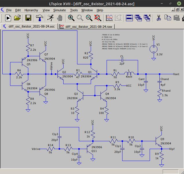
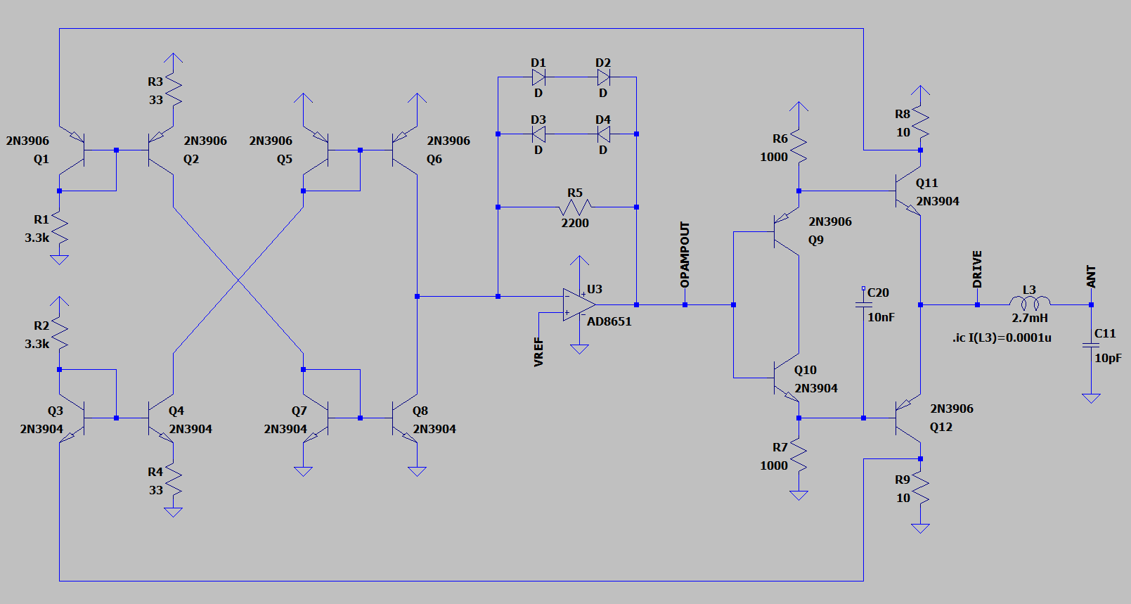
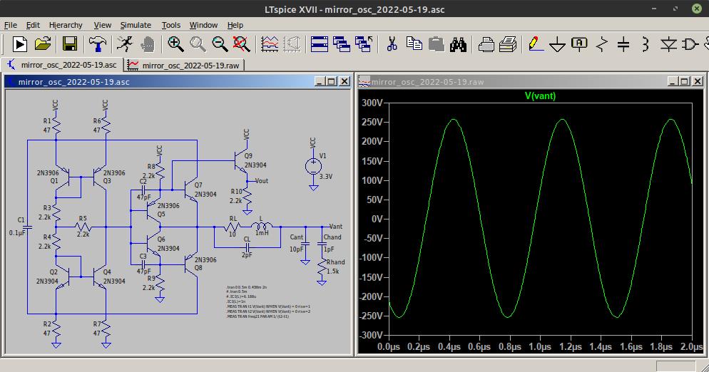
The latest 8 transistor oscillator is pretty nice, though yesterday my bench was inundated with some sort of noise that made it rather unstable out at 16.666ms delayed sweep, like 100ns or so of phase noise.  I swapped in the 6 transistor version and it was acting the same, so it doesn't seem to be the new buffer at fault, and it calmed down later last night.  This morning there is ~20ns of phase noise @16.666ms with 60Hz bursts superimposed on the drive wave.  If I kill the power the bursts are still there, so the coil is ringing to external mains interference.  But there seems to be a second interference component at work, and I've seen this sort of thing periodically through the years (crazy days and calm nights).

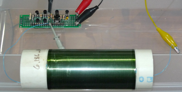
LC oscillators generally return one end of the coil to a low impedance, which might make one think would preclude this sort of behavior, but perhaps they are all susceptible to being pinged like this (i.e. an inadvertent ring down Q measurement).  I suppose sticking an antenna on a high Q coil and expecting calm seas is just sort of asking for it in the first place.

[EDIT] Here's a scope capture of the pinging / ringing:

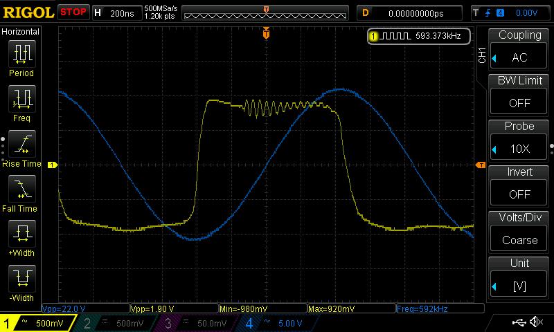
This is just one example, it can and does happen at random locations anywhere on the drive waveform.  Zooming up, I see 4 cycles in 150ns, which is about 27MHz.  There are fairly long leads on my coils, perhaps this stray inductance is doing the ringing with the capacitance of the coil (above SRF L => C)?.

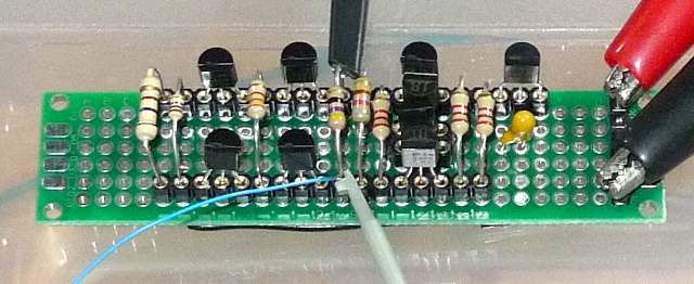
I need to get this off the breadboard and onto proper vectorboard.

Posted: 1/16/2021 7:29:38 PM
dewster

From: Northern NJ, USA

Joined: 2/17/2012

8 Transistor ECL-LC Oscillator : The Vectoring

OK, finally got the oscillator on proper vectorboard:

And here it is connected to a 6mH coil:

With 3.3V regulator it's drawing 6.75mA, 220Vpp at antenna, 592kHz.  When I power it down the frequency just barely budges as it flatlines, really amazing.  Difficult to stall w/ insulated rod antenna, no starting issues.  Still seeing the pinging / ringing described above.  My 4 xistor buffer is boffo!  (It's a subsection of an audio amplifier I designed and built for an EE lab assignment in college.)

Posted: 1/28/2021 11:25:17 AM
dewster

From: Northern NJ, USA

Joined: 2/17/2012

Ringing Source Found

It's my fluorescent desk lamp.  Turn it off and the oscillator waveforms are smooth as glass.  The bursts are at ~23us intervals, which is ~43kHz.  So it's not some random internal instability.  This is a great little oscillator, I turn it on most days just to watch it run for a couple of hours.

Posted: 9/15/2021 8:51:02 PM
dewster

From: Northern NJ, USA

Joined: 2/17/2012

10 Transistor ECL LC OSC

Been kicking this around in my head and in LTSpice for a bit:

It's just the 8 transistor oscillator described above with a 4th order low pass filter on the output.  The filter is for anti-aliasing before sharpening up the edges and digitally sampling.  Like the oscillator, the output is centered about VCC but only swings within a diode drop of each rail.  Haven't actually built it, so caveat emptor [LTSpice].

Posted: 9/16/2021 6:17:08 AM
Buggins

From: Porto, Portugal

Joined: 3/16/2017

Dewster,

Why is LP filter needed? Is Vlpf intended to be used directly by digital part or some buffer is supposed to be used? Are you sure driving of buffer (e.g. 1g04) from LP filter would give any advantages comparing to direct feeding of drive signal to buffer?

BTW, delay between inductor current and drive signal is 15ns - seems good enough.

Posted: 9/16/2021 5:50:53 PM
dewster

From: Northern NJ, USA

Joined: 2/17/2012

"Why is LP filter needed? Is Vlpf intended to be used directly by digital part or some buffer is supposed to be used? Are you sure driving of buffer (e.g. 1g04) from LP filter would give any advantages comparing to direct feeding of drive signal to buffer?"  - Buggins

My theory is when you square up the oscillator drive you're sort of sampling it and therefore "baking in" any higher frequency noise (~aliasing).  Also, it's probably desirable to band limit the signal going back to the processor board, and square it up there if necessary.

[EDIT] My ill-fated AFE did the XOR-ing in 74AHC logic, which considerably raised the bandwidth requirements of the cabling back to the FPGA, so I'm rather gun shy of any excess bandwidth anywhere.  Interference & noise should be dealt with as much as possible before non-linearities are introduced.

Posted: 10/13/2021 2:16:18 PM
Buggins

From: Porto, Portugal

Joined: 3/16/2017

I've designed current sensing oscillator with sensing of power supply of drive amplifier:


Details are in this thread

Posted: 5/19/2022 8:10:37 PM
dewster

From: Northern NJ, USA

Joined: 2/17/2012

Current Mirror Oscillator

Another variation on Vadim's fascinating oscillator:

It simulates real nice.  I had high hopes for it, but doesn't perform so well on the bench and needs a fair amount of capacitance to work - I think it's the phase error that's partly to blame.  Really low current draw, like a few mA (sim shows more).

Spice file here: https://www.mediafire.com/file/grs6ravndg0fnlt/mirror_osc_2022-05-19.asc/file

Posted: 6/16/2022 8:16:46 AM
Buggins

From: Porto, Portugal

Joined: 3/16/2017

Played a bit with this model. 
It's possible to reach 800Vpp, 40mA drive...

You must be logged in to post a reply. Please log in or register for a new account.