"I did download it but the grayness & graphics seemed clunky, I am sure it works for complicated stuff like precise digital but I am only doing basic analog circuits where ohms law and 5% accuracy of a slide-rule gives me answers." - Christopher
The FPGA tool I use can do digital a lot better so that's where I do almost all of my digital sims. LTSpice will work for mixed analog and digital, but I only use it for analog stuff. And it's not that analog sims are more accurate than reality - if anything they are only a rough approximation, so you have to take their results with a grain of salt.
"I think relying on modeling would have kept the method hidden from me as I would never have had hands on much less made anything physical."
There's a lot of serendipity to be had tinkering around on the bench, though I can muck around in a sim and quickly try a bunch of things in an hour or so that would take me days on the bench, so sometimes luck strikes there first. For me it's a best-of-both-worlds kind of thing; when I get the sim and reality to jibe then I understand the reality a lot better. Once you get past the learning curve pain, sims can be a lot of fun!
======
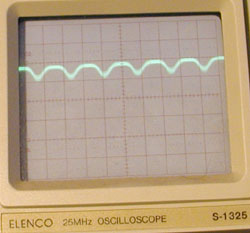
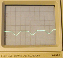
Your waveform looks a lot like clipped 33% PWM. I bet there's an easier way to get it (sans opto). The two transistor mixer I posted to the analog thread can make somewhat similar waveforms. Just a matter of mixing to something rather sine-like, then offset & clip (doable with offset and overdrive hitting the limits).