Enhancing The EtherWave Sound

Posted: 9/1/2016 12:26:17 AM
oldtemecula

From: 60 Miles North of San Diego, CA

Joined: 10/1/2014

I will do the smoke test tomorrow, today we celebrate wink

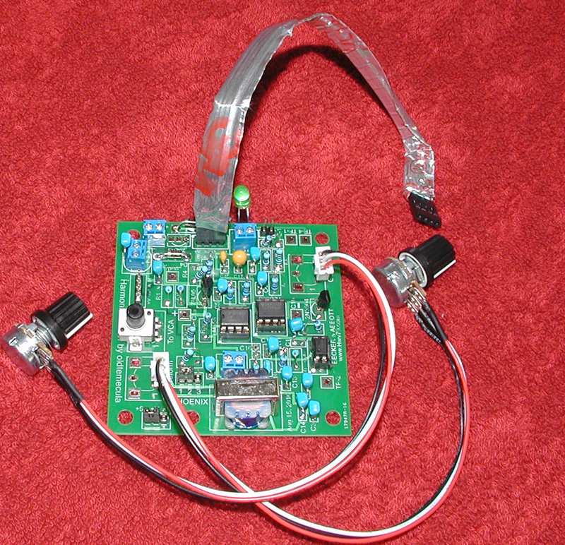
This board gives a nice vocal sound, similar to the classic Clara Rockmore voice. It is 95% the same board as my PWM volume control board. Both use the basic LM358 & TLC555. I restricted myself to only using Radio Shack parts in my first few years because I needed to develop an understanding of “less is more”.

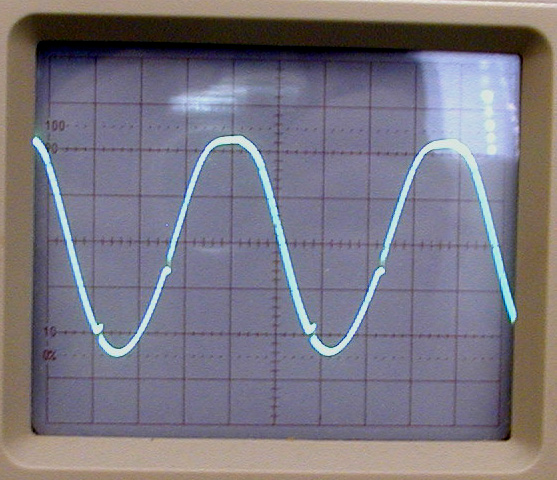
It was dewster’s penciled out emitter follower circuit that was like a secret treasure map that showed me how to advance; I waited a long time for it. My buffer/breakout board only outputs the ideal sine wave.

I will replace the EWS waveform knob pot with my own, keep the brightness and maybe drop the EWS audio output out the bottom so I can use that hole for my gain knob/pot. I placed the Opto chip in a socket so it can be removed, it has been a long time to test does it really do anything.

I own three EtherWave Standards as it is the finest theremin design till now. The goal is to set up all three, one EWS will remain normal connected to a Moog 15 watt amp, the second one will have my new 4-layer Exciter printed circuit board installed which gives the EWS a more vocal sound. It also will use a Moog 15 watt amp. 

The third EWS will seem ordinary but all the internal guts will be my own original theremin design. The amplifier will be the Behringer UltraTone K450FX if it does not dislocate my shoulder lifting it out of the closet.

Then I will want a Thereminist to test and compare these combo’s

November 13 is my birthday, seems like a good date to aim for. It will be my first theremin 3-way and hopefully it will be exciting. The theremin is the gift of Lev Sergeyevich Termen to us all. 

Christopher

Posted: 9/1/2016 6:02:10 PM
Alesandro

From: Russia, The city of three revolutions

Joined: 4/20/2013

Is it formant synth? LM358  for filter and 555 for doing exiting impulses for it? 

Posted: 9/1/2016 7:17:13 PM
oldtemecula

From: 60 Miles North of San Diego, CA

Joined: 10/1/2014

Alesandro, thank goodness...  for a moment I thought I was on the dark side of the moon and could not breath. cry

Exciter LED came on, this indicates the 555 detects an audio signal

No sound is heard at ¼” EWS output jack

S2 Triple pin needs jumper across 1 & 2 for Clara or 2 & 3 for pure sine whistle

Sound ok now but now over driven.

Connected DVM to ground, floating red probe shows RF at 282 kHz in the air.

Probing Exciter LED either side at terminal 1.4 kHz is indicated.

Issue:  Scope at pin-5 of 358 output shows 8.5v square wave, this should be a less than 5-v sine wave.   Hum…

Issue: Testing voltage at 5-volt regulator, each side indicate 10.6 volts & 9.8v Hum… ground is good

Is the 78L05 backward?   Yes !!!     First issue solved, need to change PCB half moon silkscreen for both regulators. The 78L09 was not installed fortunately as it is an accessory.

Now 5-volts at pin-8 on both IC’s ……………..cool

Modern pcb's you want to avoid removing parts and doing board damage.

Buffer board drive and Exciter Gain Pot can reduce the signal to a 4-volt sine wave, need to reduce gain resistors ratio?

Schematics are at bottom of this link.  Anyone print out the Harmonic Exciter schematic and follow along.

Remember folks this is analog, you do not push buttons to select, you dial in your sound with infinite possibilities. Most are crap!

First sample - I can not play a tune due to medical issues but you will get the idea. This is ok but not good.

The sound is a little thin partially due to using the EWS oscillators, also not dialing in as it should. Needs more diagnosing.

Issue: Ribbon Cable picking noise due to no shielding, needs study.

To that french guy, stop smiling, can't put all my sh*t next to the volume loop, you knew that. I dropped the stuff below the bottom side of the EWS wood box which is better. It gives me a place to mount my knobs and pitch preview. The single cable is flat so just a saw blade width slot is needed instead of a hole.

Christopher

Edit: Will adjust some values tomorrow by tacking parts to the bottom of the board. The 4-layers of tracks all look correct. Just need to clean up the noise, may wrap the ribbon in grounded foil.

Clara wants me to bring her a box of chocolates. Valery no smoke and it looks promising.

Posted: 9/1/2016 9:38:59 PM
Valery

From: Russia, Saint-Petersburg

Joined: 6/6/2016

Christopher, I hope that smoke will not! :)

Posted: 9/2/2016 5:40:17 PM
oldtemecula

From: 60 Miles North of San Diego, CA

Joined: 10/1/2014

I listen to nature to achieve what I do, that new photo in the TW album makes me sad.

Posting at TW is much easier than making a webpage which I will need to update eventually.

I will dull the teeth on an alligator clip to attach to the foil.

Wrapped my ribbon cable in foil, attached it and complete system shut down, oops - did it short somewhere?

Pressing on Breakout board may have shorted Negative at L12 above Q1.  If both diodes blew the spark at contact would have been heard, so I do not think so.

L12 = 3.5 ohms after a moment of settling. It needs to be folded over a little and a strip of electrician tape on top to protect it. Now you tell me yell

How could I blow two 1-amp diodes without smoke, now I am baffled.

EtherWave Schematic

14.5 vac @  Pin-2  to D3 & D2 diodes, from switched on power

After the diodes no voltage across C19 or C20 electrolytic

Using diode checker both indicate a .540v drop.

Bizarre, now everything is fine again.

That seems to be the behavior of regulator output short protection. awsome

The above Breakout scenario would have been across both regulators, which would need a minute to re-activate.

More results as the day passes, stay tuned…

Did a couple of resistor modifications to reduce gain. Parallel R2-1Meg with 220k and parallel R3-100k with 100k, may go with parallel 47k.

My simple harmonic display on the computer shows me there is some kind of interference in my sound even with the 555 pulled. Did not have this on the proto board, it may be the gain Pot with the long leash picking up interference. Ground shield on the main ribbon cable did not solve the issue... hum, needs study.

I will first isolate the Harmonic Exciter from the EWS power supply, it is a good place to start.

With the noise, here is the sound byte raw, no effects. Would you want your EtherWave to sound like this?

Time to stop for the day, need some daddy's milk, Scotch on the rocks.

Christopher

Posted: 9/3/2016 12:15:15 AM
dewster

From: Northern NJ, USA

Joined: 2/17/2012

"My simple harmonic display on the computer shows me there is some kind of interference in my sound even with the 555 pulled. Did not have this on the proto board, it may be the gain Pot with the long leash picking up interference."  - Christopher

Pots on leashes are notorious for this.  You might want to ground the metal bodies of the pots too.

Isn't analog fun!?!  ;-)

Posted: 9/3/2016 6:09:51 PM
oldtemecula

From: 60 Miles North of San Diego, CA

Joined: 10/1/2014

This theremin setup does not have a Null point, it goes ideally low then rolls over to the other side. Mute switch solves any issues.

Removed 555, this can add nice grittiness to the sound, not used in sample below.

Isolated power supply

harmonic display reveals volume control resonance noise slightly visible 

Remove Pot cables, does not seem to be it. Impedance is too low to worry about noise pickup here.

Sine wave signal C2 is almost clean, scope shows a bit of noise on peaks

.01uf at input TP-1 to ground cleans this up or can replace C5-100pf with .01uf on Breakout/Buffer board.

.0047uf (472k) better?  prevents any high frequency attenuation of audio signal.

Removed external power, EWS powering board. Signal is clean

Shielded Ribbon cable ground removed, horrible, definitely needs it.

S2 Pins set to Clara position.

Would like first stage OP gain increased slightly so VCA Pot has 1.5v to 2v to work with. Now it is at 1.2 volts with R2-1 Meg in parallel with 220k. I would keep using the R2-1 Meg resistor as other theremin designs might need the extra gain which is adjustable using tack on resistors.

Need a 10K resistor at Waveform to S2 tame hot signal . Need to break the inner track connection by drilling hole and tacking to bottom of board frown  or use a female to female pin jumper at S2 and plug the resistor into that.

The more vocal sound starts with the RF oscillators used.  The EWS is ok but my 300v NPN transistors will surprise you. I found a certain vacuum tube that gave the best results but they are impractical. Will start focusing on my original complete theremin build and that ideal vocal sound which fits completely inside the EWS box.

Sound Byte 3   If you get rid of the third harmonic sound becomes more human.

Sound Byte 4 I plugged the 555 back in for a little more grit in the sound, they probably all sound the same. LOL surprised

Christopher

Edit: I should mention again this method worked best using my vacuum tube oscillator and will work with any analog theremin design.

One method for shielding between boards is to go back and use the 3.5mm TRS jack and bring the +V to the board on a separate wire. Should not have abandoned it in the first place.

dewster that makes a lot of sense, my input and output wires are shielded now but side by side. This may be why I see a bit of distortion I do not like in the waveshape on the scope. I will set up another cable with the center two split apart and shielded from one another. Splitting the ribbon might be more flexible and better? First I will try shielding the diode output side by itself as that has very high impedance. This is very good stuff dew, where is everyone else?

Posted: 9/3/2016 11:52:17 PM
dewster

From: Northern NJ, USA

Joined: 2/17/2012

Ribbon cables can have lots of capacitance between adjacent wires.  One way to counter this is to rip the wires apart (this is what I do for the digital Theremin interconnect) - it's not pretty, but who cares.  Another way to counter this is to double up and run ground wires in between the signals on the ribbon cable (I believe this is what the newer IBM PC PATA cables do).  For digital signal integrity I once had to rip the wires apart and twist them with grounded wires (and also add source termination resistors) - ya do what ya gotta do, the analog goddess must be appeased.

Posted: 9/4/2016 7:29:40 PM
oldtemecula

From: 60 Miles North of San Diego, CA

Joined: 10/1/2014

I spend the morning trying to figure out noise or little dink marks in my sine wave. Pulled the Opto and 555 which is a good place to start.

It does not occur in the sine wave after the first OP amp but at the output of the second Op. The remedy I found to fix it was to load down the output of the second Op with a 470 ohm resistor increasing the output current. It could be an effect from driving the audio transformer. The word ringing comes to mind.

The 470 ohm loading seemed to move the top rail down a little as the top flatten a bit. This is something new for me. Needs thought as the resistor may just be a Band-Aid.  

LM358 Datasheet

I am not getting my lazy bottom waveform from the mixer diode which is the best vocal sound so this still needs study.

Also I have cables that are like the ribbon but more like a loose spaghetti wrap, this gets the input and output sleeping in different beds and giving clean results so far unshielded.

Christopher

RF causes the dink noise in the waveform above mixed in with the audio signal. The issue is finding the balance that the RF filter roll off frequency does not start attenuating the Audio signal at the higher frequencies. This is important to maintain the even harmonic skew at the top of the audio wave shape throughout its range.

Posted: 9/6/2016 8:28:52 PM
oldtemecula

From: 60 Miles North of San Diego, CA

Joined: 10/1/2014

Hello everyone,

Being this is the point of thread roll-over let's reflect on past knowledge. When dewster first saw my schematic he gave me a handful of suggestions. One was avoid high resistances when using OP Amps and try to avoid dc current flow through Pots. Makes sense at the Pot wiper for sure. Then there was roll off the RF earlier in your design. The between board cable remains unshielded, it would be nice shielded but not practical wrapping with foil.

I reduced my first OP Amp impedance from 100K down to 20k with the same gain ratio. Something magical happened as did many times in the past. Anytime my sound reflected what Lev Sergeyevich also heard, I would hear an unusual noise in the sound similar to that I remember as a kid, the sound of the Cicada bug. They re-awaken every 17 years and the outer edge of the Cicada wing is called Termen. Is it a hint or a coincidence? You can hear it on the low end at the end. Is it just noise or the sign of affection. surprised

I got the throaty wave shape back, the EWS oscillators are not the best for throaty.

Updated: Schematics are at bottom of this link.  Anyone print out the Harmonic Exciter schematic and follow along. Refresh Browser Press F5  for 9.08.16 Update

sound sample 5  “Switched on Clara”  Cicada sample

sound sample 6 - she is a screamer but...  dewster's silence has me concerned, now is not the time to sleep.

Christopher

You must be logged in to post a reply. Please log in or register for a new account.