basic experiments

Posted: 4/30/2016 3:11:53 PM
dewster

From: Northern NJ, USA

Joined: 2/17/2012

"Filtering the R.F. is possible by replacing the 12k resistor with transformer (like Rockmore theremin) or by following a RC combination. You see a so filtered shape in my video on oscilloscope"  - JPascal

I've had good luck (in simulation) using two RC low pass sections, with the impedance of the first 5 to 10 times lower than the second.  I avoid transformers because they pick up hum, are expensive, and can be difficult to buy.

"JFets are the BF245A type, which are not more in trade, better say not more produced. Similar transistors can be used."

Ya, I used J113 in the LTSpice because they are inexpensive and readily available.

"Theremin development is like building and preparing a violin. If you want a stradivari you must invest a lot of time and experience. I am limited in both, so I take the know how primarely from the old technique. Shape form fourier analysis of historic demonstrations of RCA theremin, without vibrato and volume effects, are the basic material for me. A radical reduction of electronic components is required, I am convinced."

Waveform out of the mixer is something one should definitely spend time on.

"Playing a theremin ever begins with a tuning like violin. There is no need for stable batterie. Current is very low.  I see the point, its critical for an electronic developer."

You could use a LDO regulator down to 5 or 6 volts.  Of all the oscillators I've played with on the bench they all benefit tremendously from voltage regulation.  It's the single easiest and most powerful stabilization technique IMO.

There are other oscillator forms with low current, better looking sine behavior, and higher voltage swing at the antenna that might work better.  Having the coil supply the oscillator operating current always seems to give a flattened sine (due to reverse conduction through the FET?).  Antenna voltage swing is dependent on coil Q and phase error in the drive.

"Looking on the wiring within old RCA Theremin massiv parasitic effects occour. The breadboard is thereby a good simulation of this."

There can be a strong capacitive interaction between the bottom of the breadboard and whatever you set it on, particularly metal and even wood.  I put a plastic box under my breadboard to minimize this, just a couple of inches really help here.

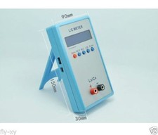
JPascal, do you have an LC meter?  I bought a cheap LC200A from eBay that works all the way down to sub pF.  It can even measure antenna capacitance if you ground one lead.  I'm wondering what the self capacitance of your 14mH coil is.  What is the resonant frequency?  Is the ferrite very temperature sensitive?  If so this can lead to long-term drift (which is why I avoid ferrite in my stuff). Does the oscillator poop out when you touch the antenna?  If so does it restart on its own?  You might want to insulate the antenna to minimize ESD issues.

Posted: 4/30/2016 3:40:38 PM
ILYA

From: Theremin Motherland

Joined: 11/13/2005

JPascal,
it's nice to see that the good old C1-94  had supplanted the German instruments in your lab wink.


As for antenna, what is the reason to do the ring at the base of the antenna? Just for to be standing?

Posted: 4/30/2016 4:38:58 PM
JPascal

From: Berlin Germany

Joined: 4/27/2016

Hi Ilya, I love my russian oscilloscops. They are very robust, easy in transport and very useful in the frequency range of a theremin. An analog tektronix 454 waits for repairing, but the spare time is rar. The circuit diagram file I named TEPMEHBOX. A tribute to the russian inventor.

Yes, the ring is for stabel standing. I tested such metal constructs from houshold stores with various length. This here makes a good linearity. My mind and experiance to the form of antennas is: you can take soucepan lids if you want. Hope nobody is angry therefore.

With this antenna I made an simple experiment. Here it is


@ dewster: My goal is to generate the conditions for an old Rockmore Theremin with Transistors. Thereby exakt sine curves are definitly not asked. The tetrode was extrem overrided on both grids and so the limiter effect and the assymmetric distortion lead to the overtones wich make the sound like an instrument. Air coils form Termens or Rockmores instrument had also temperatur drift and the resulting oscillator capacity came from tube, wire, antenna and coil. Not a moog is the aim for me. To get the old Rockmore sound I must leave the common path. Examples for measured shape forms and spice simulations I will give later. I think here is a long way to go.

Posted: 4/30/2016 5:41:58 PM
dewster

From: Northern NJ, USA

Joined: 2/17/2012

"My goal is to generate the conditions for an old Rockmore Theremin with Transistors. Thereby exakt sine curves are definitly not asked."  - JPascal  

I agree that you don't necessarily want a sine wave exiting the mixer, but I believe you want a high amplitude, well-formed sine wave at the antenna.

"Air coils form Termens or Rockmores instrument had also temperatur drift..."

Tubes make everything hot, we don't get that with well designed semiconductor circuits, particularly if they are voltage regulated and employ stable components.  I've had oscillators on my bench that snap to attention when powered up, with almost no drift even at the start. 

A ferrite coil will almost certainly have more drift than an air core coil.  Ferrite coils almost certainly have lower Q, and probably have more self capacitance.

"To get the old Rockmore sound I must leave the common path."

I believe the "secret" to the Rockmore sound is in the mixing and post processing, and that's about it.  The actual oscillator type employed is probably very secondary to the post mix sound, so it may be selected among many for whatever traits one deems desirable (mine are absolute sensitivity & high voltage).

Not trying to insult you or anyone else reading this, but it seems that a lot of people start out in Theremin design thinking there is a magical oscillator from the deep past that is more linear than the others, mixes better, etc.  It can take years to find out that (other than adding an EQ coil) this almost certainly isn't true.  After giving up on the possibility of any magic I've spent my time characterizing hand & antenna capacitance, and on working out the best digital means for signal generation and detection of this capacitance.  I for one want variable sensitivity (variable note spacing) and there are few good ways to do this in analog (unless you completely decouple capacitance sensing from tone generation).  I also want a highly responsive tuner display, and there is no way to do this with analog, or even with digital hanging off the analog.

The simple heterodyning analog Theremin is amazing in that it works as well as it does with so few components.  But it's a one trick pony, and you can only take it so far before hitting an engineering brick wall.  My advice is to learn what you can from it and move on.  Many of my most fruitful investigations have been from playing around with a few coils, capacitors, and resistors, stimulated by a function generator and observed on a scope.

Posted: 4/30/2016 7:08:48 PM
JPascal

From: Berlin Germany

Joined: 4/27/2016

Give me a chance, dewster. This trick pony is not yet exhausted :-) Take three parameters and the solution divergates for example. I want avoid "post production" of the signals. If there is a magic secret thing, then that the old RCA needs no "after shaping". Shure, you can make all digitally and with filtering, mixing all what you want. Thats no my point. I am interested in the basic investigation, not in the rather engineering and optimizing process. I see some open questions which interest me. Look at Lev Termen, he put a screw driver near the Antenna to tune it. That is geniuos...

Posted: 5/1/2016 8:48:00 AM
ILYA

From: Theremin Motherland

Joined: 11/13/2005

"An analog tektronix 454 waits for repairing, but the spare time is rar" - JPascal

"Stierlitz, you're a Russian spy!  Not because of the Russian oscilloscopes, Nein! А German would never repair his oscilloscope itself and would bring it to the service center! "


JPascal,
your graph demonstrates a good linearity. Now it is small: to obtain an acceptable thermal stability. The different schematics of your oscillators can not guarantee a correlated thermal drift of the ones. 

Posted: 5/1/2016 1:32:41 PM
dewster

From: Northern NJ, USA

Joined: 2/17/2012

"Give me a chance, dewster."  - JPascal

I'm certainly not trying to discourage you from your investigations, it's just that I've looked into a lot of Theremin aspects at a fundamental level (I've fairly thoroughly characterized hand & antenna mutual and intrinsic capacitance, performed many oscillator experiments, examined various paths to linearity, discovered the invariant, created verilog DPLLs, etc.) and I suppose I'm just trying to keep people from wasting time barking up the wrong trees.  It's a field one can come up to speed on fairly quickly with help.

Posted: 5/1/2016 8:52:44 PM
JPascal

From: Berlin Germany

Joined: 4/27/2016

Yeah, the russian James Bond, Ilya. But he looks much better then mecool. All my meters I became were defect. So I learned a lot about them by repairing them.

Your problem I understand now, dewster. Many barking trees you had overcome. Now a newcomer thinks his idea shortens all of them. Give me the circuit wich makes exactly the Rockmore sound with a handfull jFets and I look for another problem. wink

The drift of the unequal oscillators difference frequency lead to a moved zero point distance hand to antenna. The effect on playing must be tested. 

Posted: 5/1/2016 9:18:20 PM
dewster

From: Northern NJ, USA

Joined: 2/17/2012

"Now a newcomer thinks his idea shortens all of them. Give me the circuit wich makes exactly the Rockmore sound with a handfull jFets and I look for another problem."  - JPascal

Well, there are a lot of things to consider carefully, and a lot of things to ignore completely.  It takes time to know which category a particular feature is in, or even what the question is in the first place.  And of course being engineering there are often many answers that are equally fine, but sometimes there is only one that is really the best.

For instance take JFETs: is there any reason you are using them instead of BJTs?  I know people tend to think FETs = tubes, but for me this is something to consider carefully.  You can build nice oscillators with either, but BJTs are easier to buy and have more well defined specs, so IMO FETs should only be used when a BJT won't work as well.  This is just one small thing but it is rather basic.

Posted: 5/2/2016 2:52:04 AM
oldtemecula

From: 60 Miles North of San Diego, CA

Joined: 10/1/2014

Jan said: "Your problem I understand now, dewster. Many barking trees you had overcome."

Did something get lost in translation?

xtheremin8 no "Walpurgisnacht" here today though my last name is German, I was married to a witch once. surprised

Engineers: What is the best way to measure linearity of the pitch field? All of my theremins seemed to have a perfectly linear field using the closed hand open method right up to the antenna.  Today I conclude a long skinny wire antenna is best in my application but then I am fatter and have a lot of capacitive surface in the back of the playing field. If this has affect there is no perfect linear pitch field that will work for everyone, we must settle for ideal.

Also if I was standing barefoot in a puddle of water or dry on a carpet the field was still linear, the pitch field was just wider or narrower.

My vacuum tube theremins would hold the same musical note, say 300 hz over a ten degree F room temperature change overnight. The coils were kept lower than the hot tubes. This revealed to me that 95% of modern thermal drift comes from the behavior of PN junction transistor character mismatch. Any coil issue would be counter balanced by the dual oscillator design of the theremin.

I once posted my list of 13 theremin myths and many got excited because it violated their religion or beliefs. dewster brings up FET application and I agree with his opinion. That would be added to a new list. In my experiments the main trick in Clara's voice is in the RF signal mixing. I will reveal my single diode method in time so it can be improved upon. What sets me apart from most is I still believe in magic and natural vision.

Christopher

You must be logged in to post a reply. Please log in or register for a new account.