


Dewster,
I did not make a mathematical basis for calculations yet (including accuracy estimations). Maybe 100 pf (I have 99.8 pf) is enough, may be not. Certainly, it can be replaced at any moment. As for the resistances, it is not an issue, because any losses in the resonance circuit will be compensated by the negative output impedance of Q7.
C5=12pf is a recommended value for unbalanced crystal connection (AN2027). To be honest, the internal oscillator circuit of PSoC is a critical part. When I played PSoC for theremin purpose, I disabled the internal PLL and used an external clock IC (24 MHz).
----------
The driver board.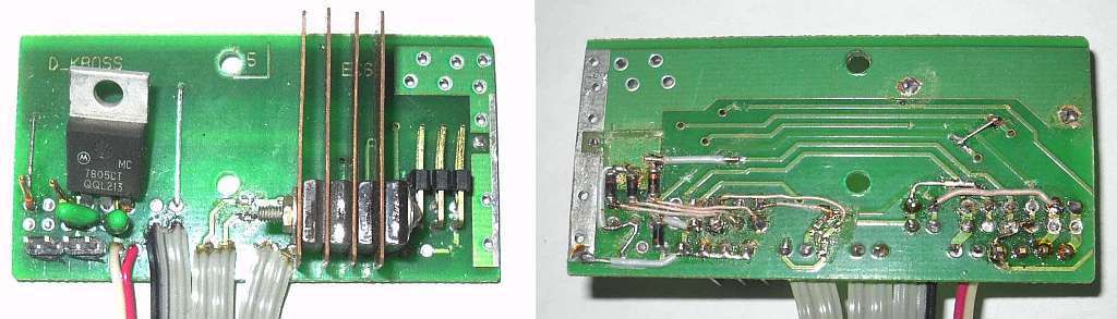
Sometimes to accelerate prototyping I cut suitable areas from unused serial boards, drill extra holes for new components, cut unwanted traces and put jumpers. Not aesthetic, but works. Ne plous, ne moeins.
The copper plates (as heat sinks) for Q1-Q4 are funny for this application, but could be needed in the future for more powerful motors.
Linearity Meter

"I did not make a mathematical basis for calculations yet (including accuracy estimations). Maybe 100 pf (I have 99.8 pf) is enough, may be not. Certainly, it can be replaced at any moment." - ILYA
It's a pretty big C and might kinda swamp your finer measurements. I can see maybe 10pF just to have a known C against which you can measure the antenna instrinsic C.
"As for the resistances, it is not an issue, because any losses in the resonance circuit will be compensated by the negative output impedance of Q7."
Not sure what you mean. All of those resistances across the tank are very real and won't go away due to any drive or Early Effect equivalent resistance of Q7's collector. I think this oscillator type / topology is maybe OK if there is an EQ inductor.
"C5=12pf is a recommended value for unbalanced crystal connection (AN2027). To be honest, the internal oscillator circuit of PSoC is a critical part. When I played PSoC for theremin purpose, I disabled the internal PLL and used an external clock IC (24 MHz)."
I meant the C5 in series with the antenna.
[EDIT] Sorry ILYA, I'm probably coming across as too critical. Almost any LC oscillator will likely work here, and none of the other things I'm yacking on about are critical.
Any criticism is welcome, I like the effect "view from the outside".
With the small C the second order effects could become the first order, I afraid.
"Not sure what you mean."
For resonance circuit the network of Q7 and Q8 looks like an one-port ("black box") with negative resistance.
"I meant the C5 in series with the antenna"
oops, double marking , my trouble. Antenna's C5 just separates the power net from the antenna. Unclear why this is not done in the Etherwave (as for me, the presence of voltage on external parts is a sign of bad design).
"For resonance circuit the network of Q7 and Q8 looks like an one-port ("black box") with negative resistance." - ILYA
I just spiced it and, like the Thierrymin FET oscillator, the wave is pretty distorted due to collector reverse conduction on the negative swing. With R15 and R16 in place, I'm seeing 1V to 21V swing @ 272,870 Hz. Without them I'm seeing a bit bigger swing and 270,042 Hz. That's a 1% change just due to resistive loading. I just don't like this oscillator for non-EQ coil Theremin use. IMO the tank should be minimally stimulated to keep oscillation alive and purely sinusoidal, and minimally loaded to keep the voltage swing and Q (and therefore selectivity) high.
"Antenna's C5 just separates the power net from the antenna. Unclear why this is not done in the Etherwave (as for me, the presence of voltage on external parts is a sign of bad design)."
I used to think a series capacitor was a good idea, but all it can do is lower SNR. I think many people forget that the antenna is always reacting capacitively, it always sees the intrinsic, and there is no way to couple anything to it (e.g. interference) other than through the intrinsic. So a series capacitor will not improve SNR because the intrinsic is already ~10pF. I think you're better off just insulating the antenna, which is a win/win for SNR & ESD.
"the wave is pretty distorted"
Yes, have complete compliance practice to simulation. In the EW this problem is partly solved by exception the capacitor from base to ground. The Miller effect is the price of that solution (the circuit becomes more sensitive to supply voltage). I plan to set an extra resistor between collector and tank.
------
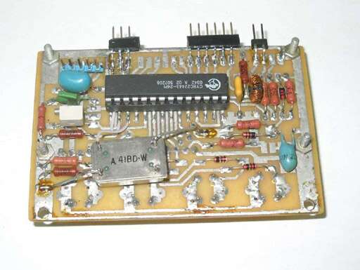
More photos.
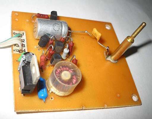
Above is the RF board. The toroidal ferrite coil is set just to start quickly (later I plan to wound an air core coil).
Platform with attached RF board: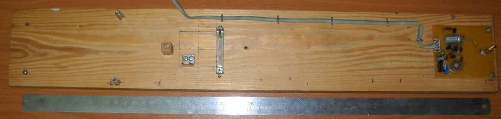
Motor stand and driver board: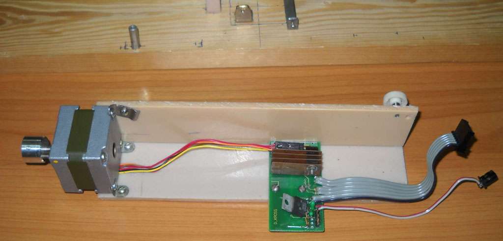
Partly assembled device in working position: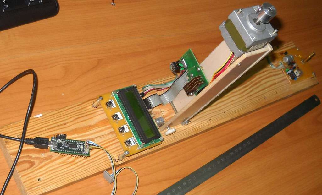
In folded position: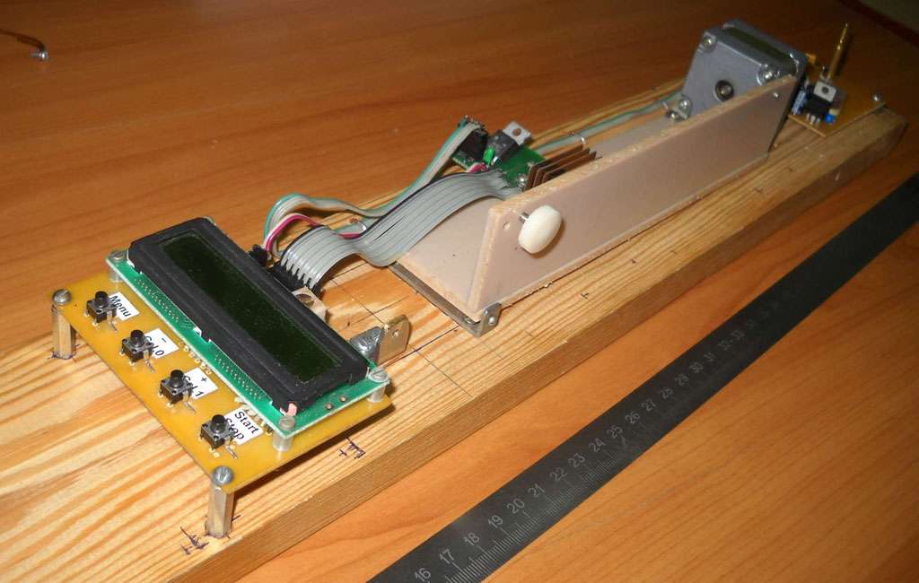
"later I plan to wound an air core coil" - ILYA
Yes, the only way to really know what's going on. My LC meter uses a ferrite coil as a reference and I'm pretty sure that's why C measurements drift significantly over time that the meter is powered up.
Dude, you are one rapid prototyper!
It's not hard when all the parts and materials are on the hands.
As I was mentioned above the watch crystal circuit with associated PLL is the problem piece of PSoC. To avoid jitter (quite acceptable for other applications), an extra 24 MHz clock IC is set.
In PSoC based theremin I sensed the dirt by ear, now I can check it numerically and compare both variants.
The components on the right side are inherited from the previous project and not used.
It's time to start coding.
Internal configuration of PSoC.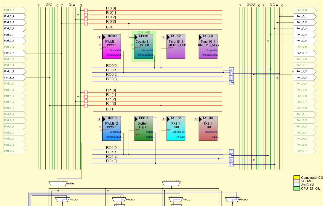
I have the PSoC Designer v4.3 installed, which is not such a monster as the latest products from Cypress.
The next User Modules are "placed" into the matrix:
Counter8_1 - 8 bit Counter for frequency meter (pre-divider),
Timer16_1 - 16 bit Capture Timer for frequency meter, also used as the 366.2 Hz (24MHz/65536) clock source for software (dual purpose),
PWM8_1 - 8 bit Pulse Width Modulator for motor control (microstep mode, phase "X"),
PWM8_2 - 8 bit Pulse Width Modulator for motor control (microstep mode, phase "Y"),
DigBuf_1 - dual Digital Buffer to pass signal between lines,
RX8_1 - Serial Receiver and
TX8_1 - Serial Transmitter for communications.
Additionally, some of the row output buffers (so called "LUT" - look-up table modules) are configured as inverters.
As you can see, the digital array (2x4) is completely filled. The matrix of analog blocks (3x4, not shown) not used.
The DigBuf_1 was required because of inconvenient pin assignment (as I try to adapt existing board). Yea, that is so far from being FPGA!
The traditional method to control stepper motors in microstep mode is to use quadrature signals (sine and cosine, or phase "X" and phase "Y"). The rotor position is determined by the ratio of winding currents. Theoretically, the PWM8_1 and PWM8_2 modules allow split each step into 256 microsteps, but this is not practicable due to the second-order effects. I plan to split each step into 10 actual microsteps (1 ustep=1 mm).
The values loaded into PWM8_1 and PWM8_2 registers will be taken from the pre-calculated sin/cos table (1/2 or even 1/4 of period to save the memory).
"I have the PSoC Designer v4.3 installed, which is not such a monster as the latest products from Cypress." - ILYA
Far and away the most massive SW on my PC is Altera's Quartus (FPGA design suite). Two older version take up ~7GB, over 100k files. Yeesh! The newer versions are even more massive pigs.
Positioning.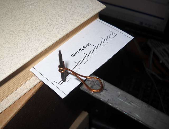
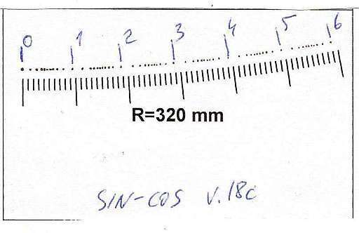
To check the microstep distances I attached the 32 cm lever with a writing unit at the end (extracted from the felt-tip pen) to the motor shaft. The sheet of paper with printed 1 mm divisions is hold by the thick book. The clearance to pen is about 1 mm. When the pen does next step, I bend the paper to put a dot. The result of the first attempt (sin-cos law) is shown below.
A little best result is reached by the linear law ("quadrature triangle waveforms"):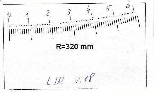
And finally, with a corrected table:
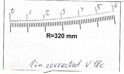
The worse case checking ("two way mode", backward after forward movement) lets me say about precision 1/2 ustep (0.5 mm):
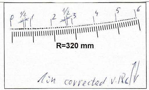
That is the result of magnetic hysteresis, plus a non-zero friction, IMHO.
You must be logged in to post a reply. Please log in or register for a new account.