Measuring Antenna Capacitance

Posted: 12/3/2016 3:59:37 PM
dewster

From: Northern NJ, USA

Joined: 2/17/2012

ILYA, I admire your rigor!

"The Moon is in Capricorn."

Ahh, I think I see the problem... ;-)

"Antenna static capacitances (w/o and with the ground plane 25x41 cm, which imitates a metal chassis)"

Many Theremins don't have a lot of metal near the antenna, so I don't think I'd take this as the norm?  Or are you just establishing a baseline for the antenna C?  Seems like a lot of metal, and that it could interfere with the oscillator in ways other than via the antenna?

"And it is necessary? The latency is completely determined by the measurement time which I choose, is not?"

Latency and bandwidth are often related, particularly when the bandwidth is low.  But they aren't necessarily related.  You could have bandwidth up to the sky and still have substantial latencies, particularly when digital circuitry is involved.  E.g. a digital delay has high bandwidth but huge latency.  MIDI has high bandwidth yet can have annoyingly noticeable processing latency.  On the flip side, the Theremini has low bandwidth but the latency doesn't seem too bad, at least to goof around on it IMO.  In unclocked (asynchronous) logic such as gates, low bandwidth (inertial delay) almost always means the latency (transport delay) is poor as well (because the underlying mechanism - an RC time constant - is the cause of both).

I suppose I'm thinking ahead to when you might be testing something like the Theremini.  There you would need a way to flutter the "hand" in a sinusoidal way at maybe 10Hz max in order to measure the bandwidth.  A variable speed slow turning fan or similar placed horizontally near the antenna might be the easiest method.  For the measurement you wouldn't be interested so much in absolute response, but mainly relative response (i.e. -3dB point).

Posted: 12/5/2016 6:32:02 PM
ILYA

From: Theremin Motherland

Joined: 11/13/2005

"I suppose I'm thinking ahead to when you might be testing something like the Theremini. ..."

I'm sorry, a little misunderstanding happened. I now understand what you mean - the implementation of a special mode for testing various theremins on latency. Interesting idea, I did not think about it.

It seems to me we must fulfill two conditions: the first is to provide an accurate (dosed) disturbance to the "arm" position (ideally it could be a sharp step), and secondly, the Meter's own latency should be an order lower than of the investigated theremin. If Theremini has a 30 ms reaction time, the Meter must have 3 ms or less. Unfortunately the arm makes noticeable relaxed oscillations every step. I will think about it.


"so I don't think I'd take this as the norm? "

yea, just an easy way to see what happens. I was surprised that the "chassis" (even such a large) is not significantly affect the static  antenna capacitance (~10%). Apparently, the supply/signal leads plus the board assembly are the dominant "ground plane".

"that it could interfere with the oscillator in ways other than via the antenna?"

The metall-to-osc influence is zeroed by the subsequent (new) calibration.

--------

Regarding to accuracy.

Each point has been measured 11 times. The table includes Average values.

The Standard Deviation in groups is 0.0038 pF, a worst case .  A capacitance resolution is about 0.0013 pF  (at operating frequency 300 kHz and sample period 0.2 s). Calibration accuracy - 0.1%.

The largest contributor to the total inaccuracy is a dimensions measurement error (0.1 mm for diameter and 0.5-1 mm for length).

Posted: 12/5/2016 6:52:06 PM
dewster

From: Northern NJ, USA

Joined: 2/17/2012

"It was surprised to me the the "chassis" (even such a large) is not significantly affect the static  antenna capacitance (~10%)."  - ILYA

I imagine you'll see more metal "chassis" static C influence with short, large diameter antennas (most area close to the plate).

Experiments like this (which I have done as well) have really helped me understand how capacitance works.  And simulations are necessary to differentiate between static C and mutual C (hand & antenna).  Static C isn't a constant, but actually decreases as the mutual C increases (i.e. as the hand approaches the antenna) - and this surprised me.  

Total C (as seen by the coil) - some constant C = surprisingly linear response to 1/(hand position).  (in terms of C that is, not Hz).

Here is the data I collected via my real hand vs. various antennas experiments (not sure why I never uploaded it before):

"Mutual Capacitance" is a misnomer: it is actually total C - a constant.  The constant is selected to make the extrapolated data slope intersect the origin.  I eyeballed this for each antenna data set with the "1/d" line.  I trust the right side of the graphs the least, as this is where my hand was closest to the antenna, and the meaning of "distance" is rather ambiguous.  (I measured it as the gap between the closest surface of my hand to the closest surface of the antenna.)  The left side data is non-linear due to the merging of my hand with the bulk of my body.  The plate antenna (7, 115mm x 235mm) is clearly the most sensitive in an absolute sense.

Posted: 12/10/2016 1:32:07 PM
ILYA

From: Theremin Motherland

Joined: 11/13/2005

Hand capacitance curves for different antenna lengths (20, 40, 60 and 80 cm) and diameters (3, 7, 12 and 20 mm):


1 s sample period, ~200 points per session (0 to 10 cm with a step 1 mm and 10 to 100 cm with a step 1 cm). A session duration is 200 x 2 x 1s = 400 s.

Every point of curve is calculated as a difference between current measured capacitance and the "static antenna capacitance". The static antenna capacitance is a value taken at the withdrawn position of "hand" (i.e at angle 180 deg.). The five latest points from every session are averaged for that purpose. The points from 50 to 100 cm are not shown.

The unhappy curve for L=60cm and d=3mm has been logged during the visit of curious onlooker and has to be remeasured. It must be said, all the measurements were performed in the empty conference hall to avoid the disturbance caused by unwanted visitors:

Posted: 12/10/2016 1:37:02 PM
ILYA

From: Theremin Motherland

Joined: 11/13/2005

Long thin vs fat short antenna

"... a long thin antenna gives better linearity than a short fat one.." - FredM from the "Theremin Linearity and Antenna Length" thread

The cases ("L=80cm d=3mm" against "L=44cm d=20mm") are presented on the graph below:


Such antennas were chosen because they have equal hand capacitances in the "start point" (50 cm). The data for L=44cm was calculated as an interpolation of the "L=40cm" and "L=60cm" cases.

It was interesting to simulate (in Excel) the behavior of conventional theremins without linearization coils:


The "zero beat" point was set at distance 50 cm using the "Pitch knob" adjusting.

Myth is confirmed

Posted: 12/10/2016 1:41:57 PM
ILYA

From: Theremin Motherland

Joined: 11/13/2005

The center of antenna is an optimal level for hand

"... to achieve optimal linear pitch interaction. I personally approach the center of the pitch antenna" - randy george

Here are two families of curves (w/o and with the ground plane shown above) on height adjustable hand position:

I believe the topmost curves correspond to the maximum sensitivity. To accurately find out the optimal height, I have done a 3-point computation for each hand distance. The results are below:

The optimal height is slightly above the antenna's center.

Confirmed

Posted: 12/10/2016 1:45:30 PM
ILYA

From: Theremin Motherland

Joined: 11/13/2005

Inverse Hand Distance low

"For all antenna geometries, the mutual capacitance is very strongly correlated to 1/distance" - dewster from the "Let's Design and Build a (simple) Analog Theremin!" thread.

I'd tried using 1/D instead of D for the x axis:

On a short segment of axis: 

More linear, but that's only a verification of the fact that sufficiently small segments of all curves can be considered as linear.


Posted: 12/10/2016 4:30:51 PM
dewster

From: Northern NJ, USA

Joined: 2/17/2012

"More linear, but that's only a verification of the fact that sufficiently small segments of all curves can be considered as linear.  MYTH: BUSTED"  - ILYA

Yeah, no.  I agree with your data (i.e. I haven't analyzed it, but it looks generally consistent with mine) but I disagree with your choice of presentation & your conclusion based on that.

My measurements with my real hand/arm/body were over a distance of 0.05m (~2") to 0.5m (~20").  

The closest distance is about as close as I felt I could semi-accurately measure with the C getting pretty high and the frequency counter reading getting pretty squirrelly.  I don't think an accomplished analog Theremin player would risk getting much closer to the antenna than this (unless they were doing it for effect - to make it squeal - and even then they generally want to avoid bumping the Theremin, and probably aren't super concerned about linearity of the squeal pitch, though non-linearity in this region probably causes some player anxiety).

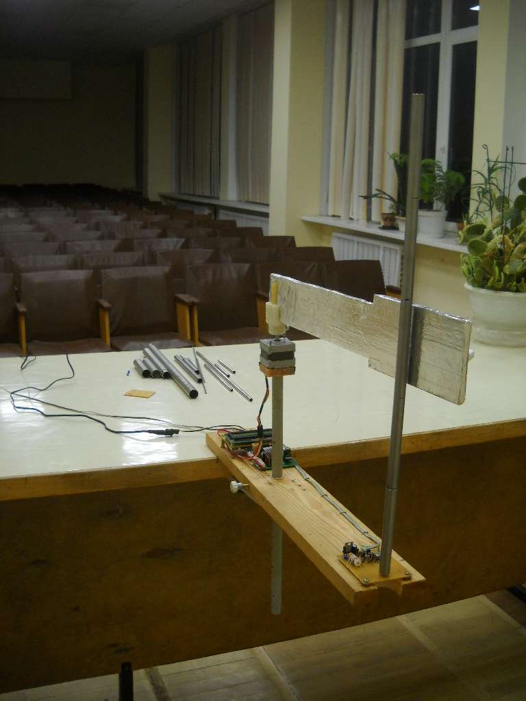
The farthest distance is my arm and hand folded up next to my body so I literally couldn't get any farther away without moving my entire body (and I certainly didn't want to do that).  Except for the presence of the motor, your setup doesn't seem to account for human body capacitance, and it doesn't really model a folding arm either.  Without accounting for these things somehow you can't exactly definitively debunk data that was obtained with a real hand/arm/body.  But, having said that, it's rather beside the point because I don't believe either of these are first order effects.

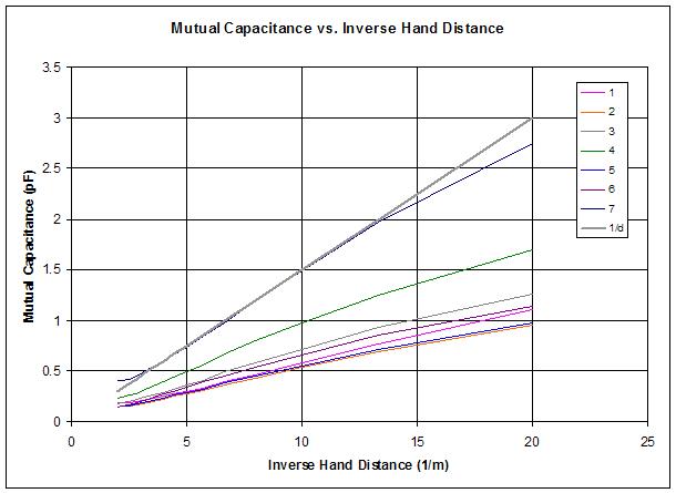
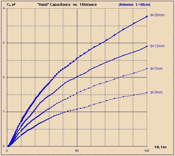
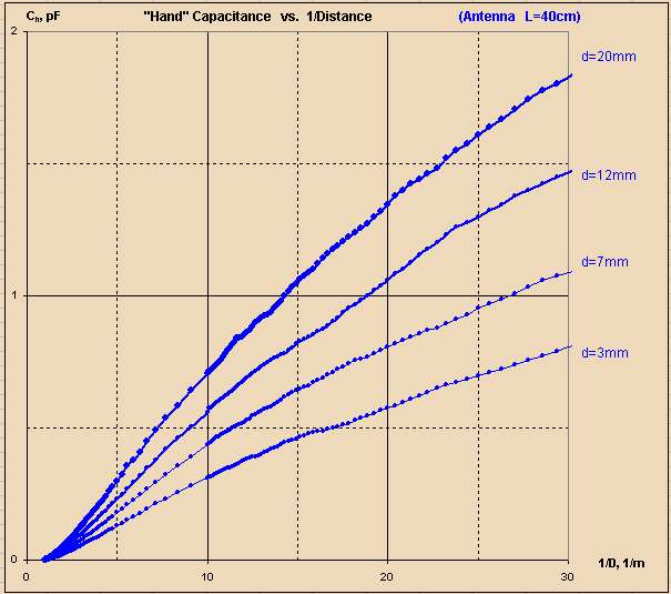
The corresponding 1/d for my measurements is 1/0.5 = 2 and 1/0.05 = 20.  With these as the x-axis (i.e. 1/d) I reported some non-linearity on the small end of 1/d, presumably due to my arm folding into my body.  For the rest I pretty much see your graph above going to 1/d = 20, which is strongly linear with 1/d, certainly better than any other numbers I've seen via heterodyning, offset heterodyning, period measurement, etc. and can be easily corrected via a mild polynomial if desired (I don't intend to).

Your top graph goes to 1/d = 100, or d = 10mm.  Your bottom graph goes to 1/d = 30, or d = 33.3mm.  The difference in distance is minor, but the marked difference in the appearance of the graphs exaggerates non-linearity very close to the antenna (a region generally avoided when playing melodically).  (Though this region on a digital Theremin that calculates back to 1/d should be much more playable than a heterodyning Theremin due to this mild drop, rather than rapid increase, in final pitch change right at the antenna.)  

tldr: No real argument with your data, but the optics between your two graphs are very poor because the brain doesn't normally think in terms of 1/d.

ILYA: I'd like to see the results of a spherical hand and a plate antenna, this was the most linear (C vs. 1/d) and also the most sensitive in my simulations.  Maybe use a 0.1m (4") diameter ball (styrofoam covered in aluminum foil) for the hand, and a 0.15m (6") x 0.3m (12") plate (aluminum flashing) for the antenna.  Perhaps try both orientations of the plate since your arm model isn't super realistic.  I'm not suggesting you do this experiment because I need any more proof (I'm convinced by my own experiments) but because it might be interesting for you and others.

And, as I've said before, I don't recommend using a rod shaped pitch antenna with digital Theremins.  It will work and provide good linearity, but a plate will provide more linearity and much more sensitivity.  My goal is to build the best Theremin possible, not necessarily the best looking Theremin in a traditional sense.

Posted: 12/11/2016 4:23:35 PM
ILYA

From: Theremin Motherland

Joined: 11/13/2005

" but the optics between your two graphs are very poor because the brain doesn't normally think in terms of 1/d."

dewster, the 1/x is your optic, mine is log(x)!


Posted: 12/12/2016 2:51:10 PM
dewster

From: Northern NJ, USA

Joined: 2/17/2012

"dewster, the 1/x is your optic, mine is log(x)!"  - ILYA

Ha ha! :-)

Not to belabor it, but the difference between your two graphs is the inclusion of a ~1" interval right at the antenna where no one actually plays.  Below is what I consider a practical playing range, and it would be even more linear with a ball hand model and a plate antenna:

Pretty damn linear, much better than anything you can get via heterodyning.  Even if it poops out a bit right at the antenna who cares?  A little pooping out is much better than going crazy and squealing IMO.

The plate capacitance formula is C is proportional to 1/d, and I believe it is exactly this if somehow there were no fringing fields.  So I guess I'm not getting where log(x) might come from?  The ear's log response to volume and pitch?  But you need to feed that with an exponential in order for it to be perceived as linear...

You must be logged in to post a reply. Please log in or register for a new account.