Hardware part:
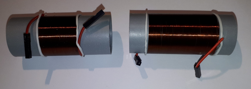
Air core inductors (25mm frame, 0.1mm wire, coil-to-coil) are ready:
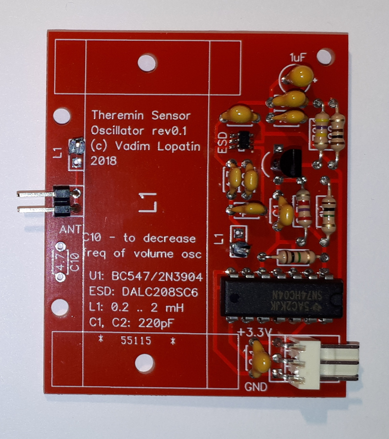
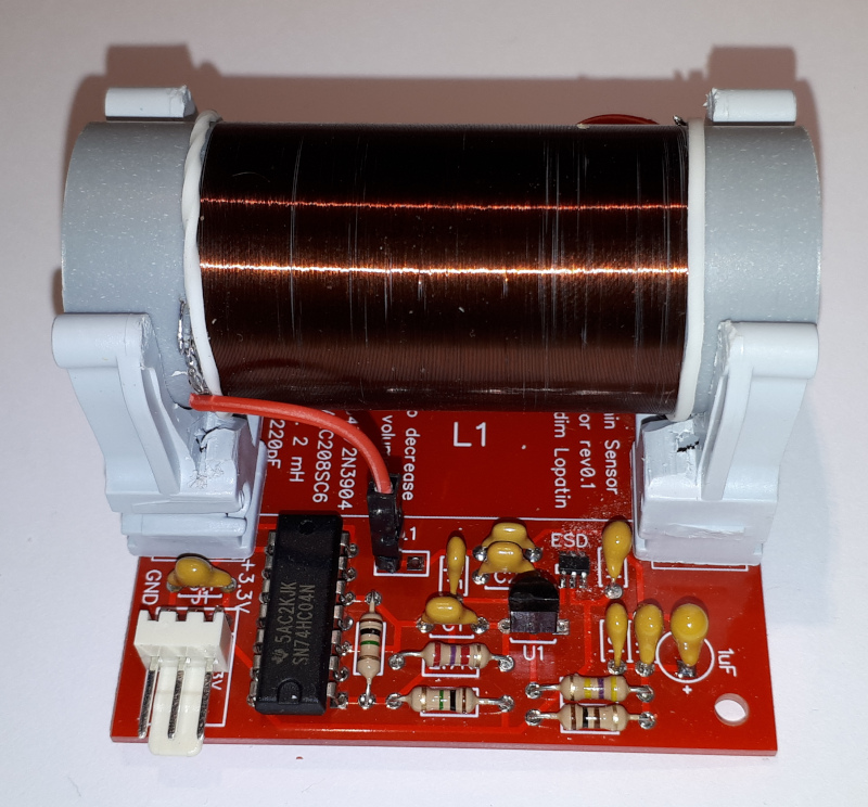
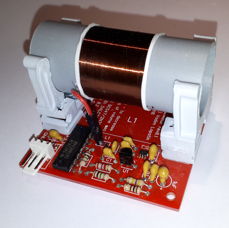
Oscillator PCBs are soldered:
FPGA part:
I2S I/O (PMod I2S2 and PMod AMP3) - tested on real FPGA board.
Oscillator boards are ready, but not yet tested 
Volume oscillator:
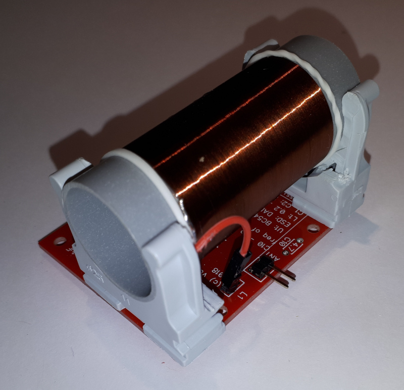
Pitch oscillator has twice shorter winding:
View from antenna connector side:
FPGA part progress: working on interrupt support and I2C control in audio I/O IP (based on I2S2 PMod and AMP3 PMod).
Lookin' good!
Is your 0.1mm coil wire diameter measured with insulation (40AWG) or without (38AWG)? I suggest you drill holes in the coil forms for the leads and run them out the openings. Nail polish works pretty good for securing the coil ends.
Is your 0.1mm coil wire diameter measured with insulation (40AWG) or without (38AWG)? I suggest you drill holes in the coil forms for the leads and run them out the openings. Nail polish works pretty good for securing the coil ends.
I'm not sure what is real wire diameter - just bought something called 0.1mm wire in local store.
I've drilled form and put thicker connection wires, coils are soldered to them. I'm coil wires may be broken.
My project status update:
I've tested oscillators using scope - seems like they are working ok.
Driver for audio I/O IP is mostly ready. Audio interrupt handler is called at 48000Hz.
Current audio i/o setup just provides output to Line Out R&L sample registers, Headphones L&R sample registers, and allows to read Line In L&R sample values.
It's supposed that CPU will generate signal in audio interrupt in current implementation.
Later it will mix both CPU and hardware synthesizer signals.
At 666MHz, ARM CPU gives me up to 13000 CPU clock cycles for generation of sample value.
I beleive it's enough for a lot of instruments.
Results of audio IRQ performance measure.
Audio ISR is called on each sample. ISR code generates triangle signale, sweeping frequency between 110 and 440Hz, and volume between min and max, writes sample value into 4 audio IO registers (line out L/R, headphones L/R)
100MHz cycles between IRQ is set and beginning of audio ISR code: 27
100MHz cycles between IRQ is set and end of audio ISR synthesis code: 230
Probably, about 30 cycles will be required to restore registers when exiting ISR (same as entering ISR).
So, about 1700 100MHz cycles = 11000 CPU 667MHz cycles may be used for synthesis.
P.S: headphones connected to AMP3 PMod sound VERY LOUD!
I2S2 PMod line out is working ok
I2C volume control for AMP3 PMod - to be tested.
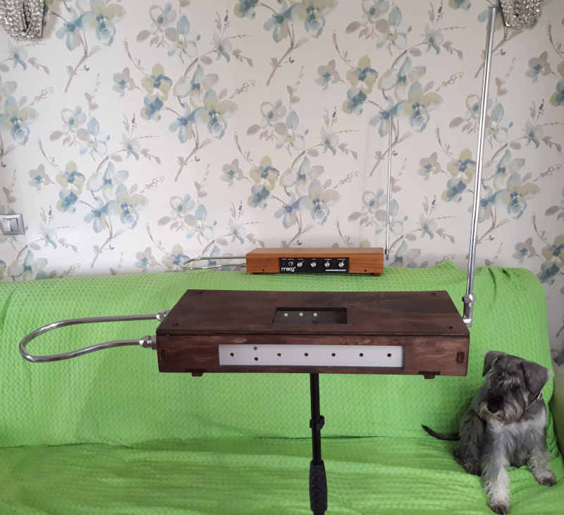
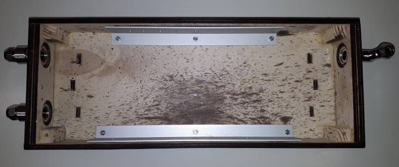
Cabinet - dark color varnish.
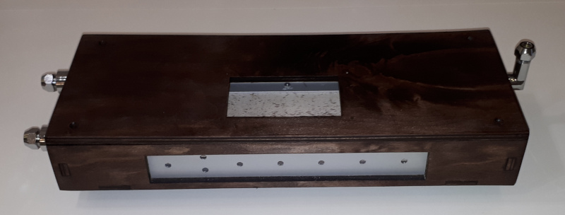
Front and rear panels - aluminum profile 40x20x2 mm.
Planned layout of front panel:
Headphones Volume knob
Headphones out 3.5mm
Mute/calibrate button
Status led
2 encoders with pushbutton
3 pots
Antenna mounts - fittings for 10mm water tube.
"Probably, about 30 cycles will be required to restore registers when exiting ISR (same as entering ISR)." - Buggins
This is one nice thing about having stacks underneath the processor registers. As long as ISR / subroutines clean up after themselves (and you do most or all of the cleaning as a consequence of coding normally), except for the call and return instructions and any setup, branching is essentially free, particularly in a barrel processor, where pipeline stalls can't happen. The downsides are the very real possibility of stack faults, fewer registers to work with, and the need to partition a project over many threads.
Do you know yet what you'll be using the rotary encoders for? I started out with 4 but ended up needing 8, but I'm not using a touchscreen, which should give you a lot more options for I/O.
General purpose CPU has a lot of things to take into account when implementing hard real time.
In Zynq ARM core, there are caches. And DRAM interface of Cora Z7 board is 16 bit.
LCD controller DMA will consume part of DRAM bandpass.
So, 10000 CPU cycles are not guaranteed at all for IRQ handler. But I believe at least half will be available in any conditions.
Complex synthesis has to be impemented in FPGA part. I'm still thinking about additive synthesis implementation. There are enough resources for it.
So far, with theremin sensor controller, audio controller and LCD controller, about 10-15% of FPGA is used.
Regarding controls, I'm not yet sure how to map them.
One of encoders will probably change pitch range (in pressed state - scale range, not pressed - move it).
Second encoder - probably, for selecting instrument / preset.
Having more encoders is hard to achieve because of lack of I/O pins. A lot of pins are used for LCD screen and touch. Although, I'm using only 12 bits for RGB data of 24. As well, there is a lack of space on front panel.
3 pots - most likely to control effects. One of them - must have - reverb. Two remaining pots - probably will behave based on instrument selected.
I immediately recognized your wave shape from Modeling is exactly the correct shape and amplitude for creating that Classic Theremin Sound. What the green wave shows if at an audio frequency, that is what creates the throaty sound, the dragging bottom. Lev Sergeyevich and I used an audio transformer to skew the wave peak for rich harmonic overtones. In your final digital design you should have access to this classic wave shape so someone could switch from their wonderful digital sounds to classic if they choose.
Christopher
oldtemecula,
Green signal on simulation is radio frequency oscillator's transistor emitter. It's very distorted to get max voltage.
Probably, if such signal would be passed through heterodyne, output waveform might be similar to original signal...
Simulation of classic theremins is nice to have or even must have for digital theremin.
The best way of reproducing classic sound is to model processes from original schematic. Find some formula which produces the same output as original device.
But it's often too complicated.
We can try linear predictive analysis to divide signal into filter and excitation. If filter will be the same for all note ranges, this method should be good for modelling of signal. If filter morphs between notes, this metod becomes similar to wavetable syntesis.
It makes sense to look at harmonics - if they change from note to note by some simple rule, formula may be written using harmonic frequencies a
Simple solution might be a kind of wavetable synth. Wavetable should have one signal period recorded for different pitch. Probably, more than one sample per octave. Waveform for any note will be calculated using interpolation between two nearest recorded waveforms.
Probably, waveform depends on volume as well (e.g. becomes distorted at higher volume).
For building simulation of instrument, it's necessary to collect samples of instrument sound for different pitch. If someone has real device, samples may be collected e.g. by moving from min to max note, with stops several times per octave.
For some instruments, there are recordings (e.g. Clara), from which some samples may be extracted (from fragments w/o acompaniment).
Don't you know where to find collection of classic theremin sound samples?
You must be logged in to post a reply. Please log in or register for a new account.