Yes, that looks like plenty of hardware to do just about anything! You probably have enough memory even in the FPGA BRAM to do small reverbs and delays.
There are 512MB of SDRAM which is accessible via AXI. I'm already using it to read frame buffer data for LCD. It would be easy to add one more channel for audio I/O: reverb, some extra large WaveTable instrument data access, even DMA based (vs interrupt based) Audio IO from PS(ARM) side.
Too bad there isn't a bit more in the way of FPGA pins broken out to headers, there are probably gobs of unconnected pins, though I imagine the touchscreeen will give you lots of GUI I/O options.
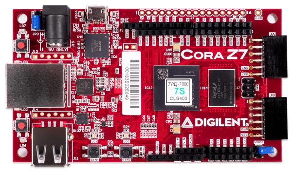
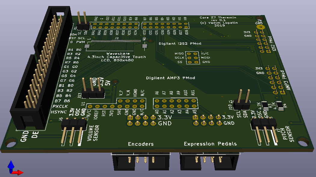
I've managed to fit most of connectivity into Arduino/ChipKit connector (+SPI connector).
Two on-board PMOD ports are left free - it's 16 free pins.
Anyway, there are 5 encoders, one button, 6 analog inputs (expression pedals with pots) and unlimited functionality of big enough touch screen.
I believe, up to 6 pedals may be used for controlling of effects, and/or for features like LOOP, recording, etc.
I wonder how long that ARM9 embedded inside the FPGA takes to boot up into a useful state? I suppose you could run it bare metal, but then I imagine you wouldn't have the benefit of a file system?
AFAIK, FPGA loads its configuration from flash. But probably, PS (ARM) may load configuration from filesystem.
I didn't measure boot time. But I didn't see any delays in booting.
(E.g. power up -> test image on LCD was been displayed almost instantly - less than 1 second AFAIR). Let me recheck it.
Of course, I'm using bare metal mode (so far, only one ARM core). It's not hard to implement SDcard driver for bare metal (there are such drivers for FAT on SD even for Arduino). Since there is FPGA, it may implement hardware acceleration with DMA for reading/writing SD card blocks.
Of course, complex filesystems (e.g. NTFS) are too hard to implement. But FAT is pretty simple.
SD card may be used for storing instruments (configurations, wavetables, etc), accompaniments in MP3 or some other formats (ARM is enough for playback), for recording of theremin performance as audio file.
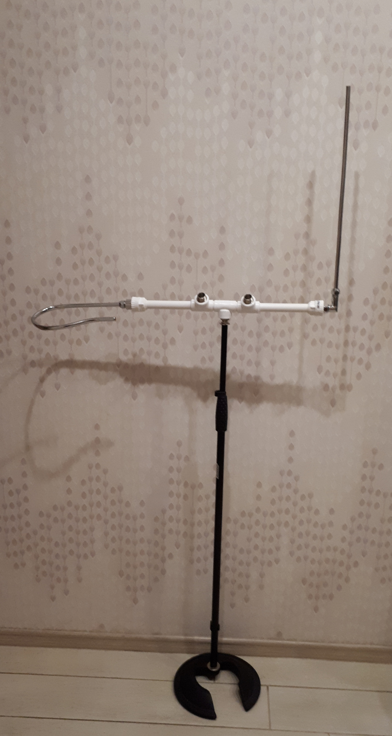
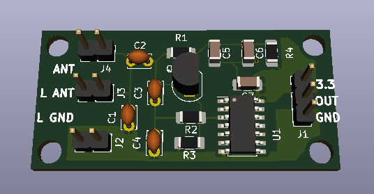
How will you be making electrical contact with the antennas?
There are two fittings for each antenna (ppl->metal) - one on antenna side, one on cabinet side. They should be connected with wire inside pipe.
Two 1/2" fittings used to mount cabinet will be used as antenna contacts.
As well it would be useful to pass grounding to middle fitting - mic stand (e.g. via volume antenna side mount) - it could improve antennas sensitivity (act mostly as a real grounding).