Let's design and build cool (but expensive) FPGA based theremin

Posted: 12/13/2022 1:54:29 AM
dewster

From: Northern NJ, USA

Joined: 2/17/2012

"Do you have any experimental proof that active shielding does work?"  - Buggins

Alas, no.  Though FredM experimented with it.  Lately I've looked at The Burns oscillator and an old 555 from the junk box, not exactly super stable, but probably OK for smaller fields and such.

Posted: 12/15/2022 3:36:38 PM
Buggins

From: Porto, Portugal

Joined: 3/16/2017

Monitoring of FPGA boards available on market.

QMTech Zynq board for $60 seems to be disappearing. 1 left in stock on ali QMTech store. Doublechecked - the comment about 400MHz max SDRAM frequency due to bad PCB routing was related to this board.
So anyway it was a bad choice.

All Trenz boards are still out of stock.


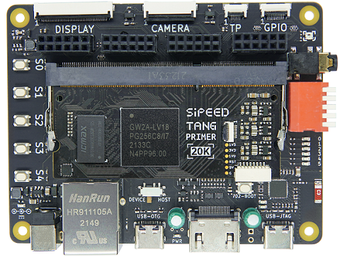
Tang Nano 20k - a lot of sellers, different base boards available. $30-$50 depending of carrier board.
The Gowin FPGA chip resources (20K LUTs) and onboard SDRAM - more than enough for digital theremin build.
Main stopper from usage of this board - absense of simulation in Gowin IDE out of the box.


By search request like "Zynq FPGA Board" on EBAY and Aliexpress, most suitable low cost board is MicroPhase Z7-Lite.

A lot of sellers. Prices for Z7010 start from $100, for Z7020 - from $150.


For me, Z7-Lite looks like the best candidate for digital theremin core.
I/O banks available on 2*40pin GPIO headers are powered from 3.3V.
With AD9833 as sensor drive signal source, no LVDS outputs are needed. Outputs to AD9833 are just single ended clock + 3-wire SPI.
Only two LVDS differential inputs (if we decide to try minimizing line transmission noise) need to present on FPGA board per sensor.
Xilinx Series 7 allows LVDS inputs on 3.3V bank if external 100 Ohm terminating resistor is used. The only concern - external terminating resistor should be placed as close to FPGA chip pins as possible.
But we only place terminating resistor outside the board - behind connector. It should be still better than single ended input.

Posted: 12/17/2022 5:18:54 PM
dewster

From: Northern NJ, USA

Joined: 2/17/2012

"For me, Z7-Lite looks like the best candidate for digital theremin core."  - Buggins

These processor-centric FPGA boards do look attractive as the basis for a digital Theremin.  Don't really need the HDMI or Ethernet ports, but if they're free...

I assume those are voltage regulators at the lower left above the GPIO1 bank?

Typically high FPGA current draw though, perhaps due to the 45nm process?  All we really need is a small FPGA to handle critical timing, too bad processor internal peripherals can't do high precision pin event timing.

Posted: 12/17/2022 7:20:28 PM
Buggins

From: Porto, Portugal

Joined: 3/16/2017


These processor-centric FPGA boards do look attractive as the basis for a digital Theremin.  Don't really need the HDMI or Ethernet ports, but if they're free...

Having HDMI for free is nice. There are a lot of small size HDMI LCDs (targeted to RPI). But main issue with them is touch panel interface.
Some of screens assume that USB port will be used for powering of LCD and touch screen interface as HID.
On another Zynq board (Cora Z7) I didn't manage to get USB slave to work in standalone configuration (w/o OS). Usage of Linux just to interface with USB is an overkill...
Need to check if USB OTG Phy IC used on Z7-Lite can work on bare metal.
It simplifies theremin build if it's possible to use LCD+touch working via HDMI+USB for GUI+controls.
I've seen another options for touch, like I2C or SPI connected to RPI via GPIO pins.

I assume those are voltage regulators at the lower left above the GPIO1 bank?

Yes. As I see on schematics, there are 4 regulators, 1.0V, 1.8V, 1.5V, 3.3V with 2.2uH inductors. Exact type of regulator is not specified - no BOM.

Typically high FPGA current draw though, perhaps due to the 45nm process?

2..3A 5V power supply is usually recommended for similar Zynq boards.

All we really need is a small FPGA to handle critical timing, too bad processor internal peripherals can't do high precision pin event timing.

Zynq looks like overkill here. Actually it may perform the sound synthesis using one of its CPU cores (6000 clock cycles per audio sample is really a lot).


Cheap Gowin GW1N FPGA mainly for sensor and some small powerful MCU board like Teensy4.1 should be enough for digital theremin.


BTW, Tang Primer 20K with full carrier board has HDMI + USB as well...

It has FPC connectors for LCD and touch as an alternative.
Four PMOD connectors may be used for connecting of theremin sensor AFEs and audio boards.
It even has audio output. Need to check if it's DAC based or simple line out with RC filter for FPGA side sigma-delta DAC.


Posted: 12/18/2022 11:00:42 PM
Buggins

From: Porto, Portugal

Joined: 3/16/2017

Some ideas regarding cheap but precise theremin sensor compatible with MCUs.

Let's take cheap small FPGA as a base.

AD9833 clean sine drive looks attractive. But one chip costs $12.
It could be replaced with direct digital synthesis inside FPGA with external DAC.
With DDS inside FPGA we know exact zero crossing position with subsample precision, and may avoid detecting it using drive signal feedback.
But fast 8-10bit DACs cost as AD9833 or even more expensive, and with smaller stock (issues with purchase in future may be expected).
Can we get DDS sine drive for (almost) free?
What if we replace expensive DAC with simple R2R ladder + opamp buffer?
R2R matrix costs $1-$2. What should be R resistance? What is max sample rate for R2R+cap+opamp based DAC?


Current sensing approach requires comparator which senses current through drive resistor.
Comparator cost is about $5-$7 (e.g. adcmp601).
Can we get current sensing comparator for free?
FPGA pins which support differential input have built-in comparator.
What if we can use it to sense current through drive resistor? Not sure about common mode range supported by this comparator.
If not possible, ok, let's use external comparator.

Gowin GW1N series 1K chips are in stock on Mouser for $7 / 1 pcs.

Some bigger chips provide interesting additional features. E.g. embedded RAM.

Example: GW1NR-LV4QN88C6/I5 is in stock on Mouser and about $19 / 1 pcs.
It has 8MB SDR SDRAM with 16bit data width - enough for reverb/delay, and for LCD framebuffer.
QFN88 is a bit hard to solder, but I think it is possible to order PCB assembly on JLCPCB.

If FPGA is cheap we can use separate chip per sensor to minimize mutual influence, and place sensors closer to antennas.

But probably, it's ok to use single FPGA for both sensors.
R2R DAC may be connected to different I/O banks, powered from separate LDO regulators.
It makes sense to make FPGA to DAC traces short, so connectors for both inductors will be close each other.
Does it make sense to use some shielded RF connection (SMA + coaxial cable) to connect both inductors with minimal interference between pitch and volume oscillators?

How to interface FPGA sensor with MCU?
MCU should be able to fetch sensor data with minimal CPU consumption. In ideal case, one measure per audio sample should be provided to MCU.
I2S looks like ideal for this. 48KHz, 24 bits per sample, stereo. 4 pins - MCLK, BCLK, LRCK, DATA.
24bit L/R samples will transferred from FPGA to MCU via I2S will hold values for pitch and volume - e.g. linearized hand position, or even pitch frequency + volume gain.
MCU will be able to receive I2S data using DMA, with handling of received data in audio IRQ - once per audio frame.

For controlling of FPGA part (e.g. setting calibration parameters, linearization parameters, etc) or reading some data we can use SPI interface.


How to program FPGA?

Option 1: JTAG connector for FPGA.
Option 2: programming via SPI slave - bitstream will be loaded into FPGA by MCU on startup.


Audio output.

Some audio codec chip (e.g. SGTL5000) may be used for Line In, Line Out, HP Out.
MCU will output sound via I2S interface.
With big FPGA, audio stream may be passed through FPGA for post-processing, e.g. applying some filters, effects (like reverb).
FPGA as well may mirror audio stream to S/PDIF output.

LCD and GUI.

Big FPGA may hold framebuffer, and MCU may draw UI via SPI using commands like fill rectangle, draw text, etc.


Posted: 1/10/2023 4:48:26 PM
Buggins

From: Porto, Portugal

Joined: 3/16/2017

Found interesting tweets from Sipeed.

1) Small FPGA board with 20K LUTs


New #FPGA TangNano 20K coming soon~
SIP low latency SDRAM instead of DDR3 or PSRAM, upgrade BL702(USB2.0 FS) to BL616(USB2.0 HS OTG),
Add external pll chip MS5351 to gen accurate clk~
Special design for retro games, on board codec+pa for speaker, and support PS2 joystick~

2) FPGA board with 138K LUTs and hard RiscV core is announced


After Tang Primer 20K, Tang Mega 138K is in schedule now~

More than 7Mbit SRAM, 600 Multiplier, SerDes upto 12.5Gbps, hardcore x8 PCIe2.0, DDR3, MIPI DPHY, and hardcore 800M RV32 with MMU inside~


Posted: 1/13/2023 5:26:15 PM
ekahn

Joined: 11/2/2022

Found interesting tweets from Sipeed.1) Small FPGA board with 20K LUTsNew #FPGA TangNano 20K coming soon~SIP low latency SDRAM instead of DDR3 or PSRAM, upgrade BL702(USB2.0 FS) to BL616(USB2.0 HS OTG),Add external pll chip MS5351 to gen accurate clk~Special design for retro games, on board codec+pa for speaker, and support PS2 joystick~2) FPGA board with 138K LUTs and hard RiscV core is announcedAfter Tang Primer 20K, Tang Mega 138K is in schedule now~ More than 7Mbit SRAM, 600 Multiplier, SerDes upto 12.5Gbps, hardcore x8 PCIe2.0, DDR3, MIPI DPHY, and hardcore 800M RV32 with MMU inside~

I have the Tang 4K and 9K, I think the 9K on paper is an ideal candidate to replace the Altera FPGA in the D-Lev.
Usually what holds Westerners back with these kinds of Chinese components is the reliance on poorly translated spyware toolchains. But, as we speak the apicula project is reverse engineering the bitstream format for the Gowin FPGAs and adding support to the yosys/nextpnr hardware abstraction tools - and they just added initial support for hard PLLs (though only at a fixed frequency and only on the 1K).

Sipeed's English documentation is admittedly shit. But Lushay Labs is doing a great job packaging and documenting all the open source tooling for this line of FPGAs, and just released a VS Code plugin which lets you get a Tang Nano compiled and flashed in 10 minutes. It's faster than installing Arduino -- I have no idea who they are or what chip manufacturer is paying them, but they're certainly getting their money's worth. Stuff like this as well as Silice and PicoRV make it an exciting time to be a hobbyist FPGA developer! (Which I wouldn't call myself. Yet!)

Either way, as time permits, I think an achievable "evaluation step" might be to get this code running on a Tang 9K, along with a surface-mount carrier board to recreate the AFE.

buggins, are you on the D-Lev Discord? It's a little quiet in there..

P.S. if you are interested, I found Chinese documentation on those AC608 "Stamp" modules for Cyclone IV (they are made by a company called Xiaomeige), ordered a few of the EP4CE10 variant, and started working on getting their footprint and symbol information into KiCad.

Posted: 1/16/2023 3:19:45 PM
Buggins

From: Porto, Portugal

Joined: 3/16/2017


I have the Tang 4K and 9K, I think the 9K on paper is an ideal candidate to replace the Altera FPGA in the D-Lev.
Usually what holds Westerners back with these kinds of Chinese components is the reliance on poorly translated spyware toolchains. But, as we speak the apicula project is reverse engineering the bitstream format for the Gowin FPGAs and adding support to the yosys/nextpnr hardware abstraction tools - and they just added initial support for hard PLLs (though only at a fixed frequency and only on the 1K).

Sipeed's English documentation is admittedly shit. But Lushay Labs is doing a great job packaging and documenting all the open source tooling for this line of FPGAs, and just released a VS Code plugin which lets you get a Tang Nano compiled and flashed in 10 minutes. It's faster than installing Arduino -- I have no idea who they are or what chip manufacturer is paying them, but they're certainly getting their money's worth. Stuff like this as well as Silice and PicoRV make it an exciting time to be a hobbyist FPGA developer! (Which I wouldn't call myself. Yet!)


As I understand, apicula does not support BRAM and DSP so far (bitstream reverse engineering is not completed in this part?).
Once missing features of Gowin platform supported, such toolchain would make GW1N a good choice.
In particular, missing simulation in Gowin IDE is a kind of stopper for me.
But Lushay Labs tutorials show simulation using open source tools from apicula toolchain.

What is good in Tang 9K is an embedded SDRAM (8MB).
It allows to implement things like buffer for reverb, and framebuffer for LCD screen.

What is good with GW1NR chips - they are available in stock, cheap enough, and may be soldered manually (QFN package).
There is a cheap RV-debugger board which can provide USB JTAG+Serial for your custom FPGA board design.

9K is a top configuration for GW1N series.
If Eric's D-Lev firmware already occupies ~8K LUTs, it makes sense to look for bigger FPGA as a replacement.
Upcoming Nano 20K board (for $20-$30) looks as a nice replacement for Altera core board assuming there is a full toolchain available.

Posted: 1/17/2023 4:12:17 PM
ekahn

Joined: 11/2/2022

As I understand, apicula does not support BRAM and DSP so far (bitstream reverse engineering is not completed in this part?).

Yes, I figured this out last night after an initial read-through the documentation for Yosys. The other big issue is that it only supports Verilog and not SystemVerilog. Probably not a good home for dewster's work, at least for the moment, then.
But, one of the main devs is working on Gowin feature support actively and updating his project on Twitter and Mastodon. And I wouldn't be surprised if there is some dark money flowing into the project, let's say from VC-backed tech startups that desperately need an inexpensive FPGA in their project but can't rely on the Gowin tools.

To free up a little more logic for dewster's project I am planning to design a new board around EP4CE10 SOM that you posted here a few months ago. As well as shielded antenna connections and a grounded power supply. But it's not a good part to recommend for building a project from the ground up.

There is a cheap RV-debugger board which can provide USB JTAG+Serial for your custom FPGA board design.

Yes, and Tang Nano boards ship with JTAG + USB debugger on board. It's quite nice.

In the end, it's clunky but probably cheap enough to just solder in an entire Tang Nano for small volume production or early prototype. Although with the 20K you can start with a SO-DIMM socket and it wouldn't look quite so ugly.

For your project, if you haven't decided on a main processor yet, it looks like some of the Lattice parts are starting to come back into stock, and they are the original and best supported by yosys/nextpnr tooling. Then if the whole project is built inside that environment, in *theory* it could be ported to Gowin parts once the backend improves.

Orangecrab might be a great development platform? If it can run Linux at an acceptable speed inside a RISC-V soft core, surely it should be able to run a theremin. And Greg Davill really knows what he is doing.

Posted: 1/17/2023 5:16:48 PM
dewster

From: Northern NJ, USA

Joined: 2/17/2012

"Orangecrab might be a great development platform? If it can run Linux at an acceptable speed inside a RISC-V soft core, surely it should be able to run a theremin. And Greg Davill really knows what he is doing."  - ekahn

That looks interesting!  The Feather form factor doesn't allow for nearly enough FPGA I/O though, and the DC/DC converter might be a problem.  The 48MHz Xtal might be a better fit for the required clock frequencies though.  I wish these boards were geared more towards FPGA use than soft processor platforms.

You must be logged in to post a reply. Please log in or register for a new account.