"Paradox"

Posted: 8/27/2018 4:15:13 PM
ILYA

From: Theremin Motherland

Joined: 11/13/2005

"Good luck, and please report on your progress!" - dewster (from here)

ok dewster,
that theremin is finished now:


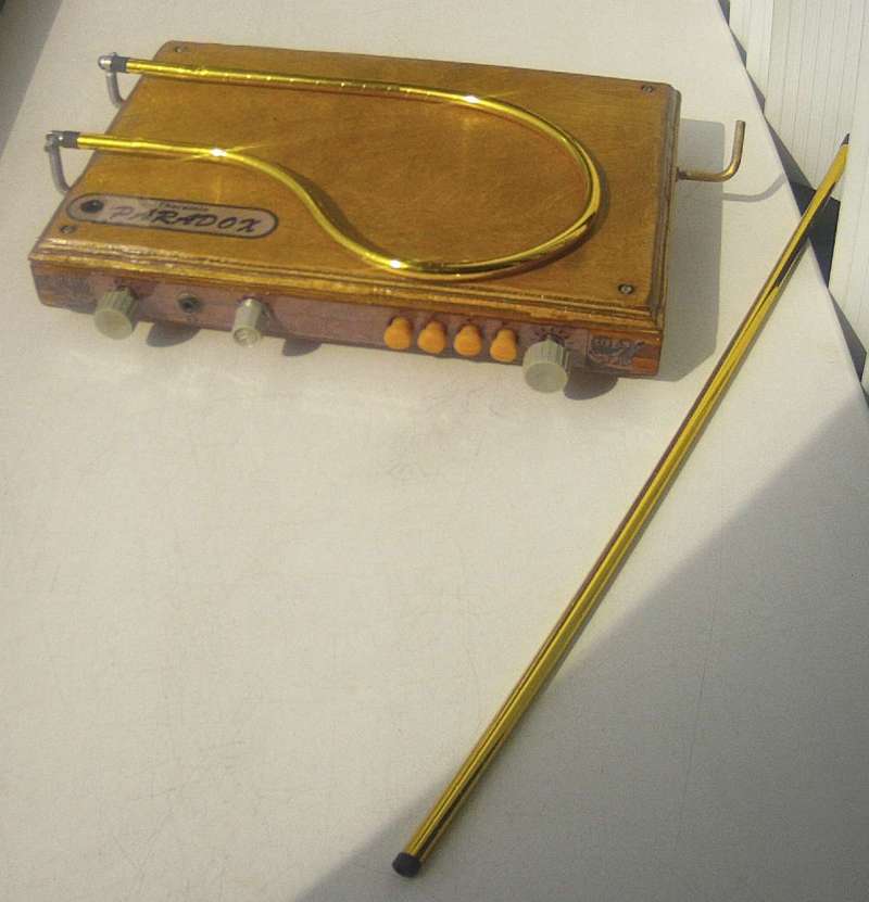
Lets recall the main ideas:
1. Using the MHz oscillators and extra dividers

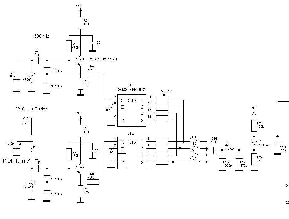
2. A common fixed oscillator for both the pitch and volume channels.
3. The TV audio amplifier AN5265 as a VCA.

A full description of project is available on my webpage (link, English auto translation)
(or in Russian).


The sound samples on different combinations of S4 ... S1 (named as 1', 2', 4'  and 8' registers) can be listen here:

"bass" group
 demo1.mp3 - register 1'
 demo1-2.mp3 - registers 1'+ 2'
 demo1-4.mp3 - registers 1'+ 4'
 demo1-2-4.mp3 - registers 1'+ 2' + 4'

"tenor" group
 demo2.mp3 - register 2'
 demo2-4.mp3 - registers 2'+ 4'

"alto" group
 demo4.mp3 - register 4'
 demo4-8.mp3 - registers 4'+ 8'

The loudness of  "soprano" register (8') is quite small due to low cutoff frequency of  C16L4C17 filter (can be corrected if desired).

The audio across the "line output" (headphones jack) was recorded "as is", but a bit of reverberation was added in second half of each track.


Posted: 8/28/2018 1:44:28 PM
dewster

From: Northern NJ, USA

Joined: 2/17/2012

Bravo ILYA, I'm very impressed!

Using a single reference oscillator for both sides, with the volume stimulus off of the 1/2 tap, is brilliant!  I really like the design of your variable capacitors too, simple yet effective.  Your selection of a logarithmic audio voltage controlled power amplifier is interesting.

Very nice background discussion as well, with linearity / sensitivity graphs, and your robotic C measurements.  The inclusion of that level of theory really separates the men from the boys ;-).

The volume side and mixer are particularly interesting to me as I have almost no experience here.  Not surprising that you had to moderate the volume side Q, the response of really high Q is probably overly snappy?  The volume drive / sense circuitry itself is quite nice, not relying on coil taps.  

I like the timbres you are getting!  Though it seems removing coupling takes some of the excitement out of the lower end, something I never considered until it was mentioned to me by a person who put an ESPE01 in their EW.  Maybe you could do some simple waveform distortion?  I've read that a rectified sine has very similar spectra to a sawtooth.  Also, have you considered formant filtering for vocals?  Three or four simple bandpass filters can open up a whole new world IMO.  One thing that I've noticed with articulated formants is that if all are articulated in the same way you get the classic "meowing" sound, but if one or more is fixed (nasal resonance in particular) the result is much less offensive.  So the inclusion of one or more fixed filters might help the overall sound from that angle?  Just thinking out loud.

I really like your approach to all of the critical elements of design & implementation!

Posted: 8/28/2018 8:27:56 PM
ILYA

From: Theremin Motherland

Joined: 11/13/2005

thanx dewster on warm words!

An extention timbre module is a next step. I still can't decide on ideology -- will it be a set of fixed timbre boards,
or a single complicated featured board which is similar to old-style analog computer.

In any case the  formant filterbank is a thing "must-to-have". I'll bear in mind your notice on fixed formants.

"you had to moderate the volume side Q, the response of really high Q is probably overly snappy"
 
The moderation is just to make the circuit behavor more predictable under unpredictability of coil's Q. Perhaps a snappy responce is more preferable for me so I'll remove the R19.

Posted: 8/31/2018 5:52:41 PM
Buggins

From: Porto, Portugal

Joined: 3/16/2017

ILYA,

Thank you for sharing your project!
Really amazing. Detailed article is awesome!

Using register switches is really interesting idea.
What if instead of switches use a kind of pot mixer - to mix % of /2, /4, /8, /16 instead of just on/off?


I'm playing with LTSpice model of 4066 based mixer.
Did someone try it?
With it, it's easy to produce clean triangle or PURE sine wave while mixing square reference and variable frequencies.
When passing square as both input and control - triangle is generated after filtering of output.
When input signal is sine instead of square (control is still square) - output will be clean sine.
4 pots may be used to mix /2 /4 /8 /16 to produce some nice waveform.
Of course, such mixer will has much more parts than your simple diode based design. Probably, strange waveforms produced by your mixer may sound better than clean triangle/sine combination.

Posted: 8/31/2018 7:22:30 PM
ILYA

From: Theremin Motherland

Joined: 11/13/2005

"When input signal is sine instead of square (control is still square) - output will be clean sine."

Fred M proposed this technique several years ago (with the PWM on control input to implement the volume control)

"When passing square as both input and control - triangle is generated after filtering of output."

it will be not a clean triangle: the alias (unharmonic) frequencies will be present in output audio signal.

Buggins,
I just tried to find a reasonable compromise between schematic complexity and sound quality.

Posted: 8/31/2018 7:48:11 PM
Buggins

From: Porto, Portugal

Joined: 3/16/2017

"When input signal is sine instead of square (control is still square) - output will be clean sine."Fred M proposed this technique several years ago (with the PWM on control input to implement the volume control)"When passing square as both input and control - triangle is generated after filtering of output."it will be not a clean triangle: the alias (unharmonic) frequencies will be present in output audio signal.Buggins,I just tried to find a reasonable compromise between schematic complexity and sound quality.

PWM volume control is very interesting idea.

Is aliasing similar to XOR+filter result?
I'll try to simulate triangle for long period and check FFT. Can we trust LTspice results?

If triangle won't work, we still have pure sines.
Probably, mixing of sines might produce some interesting effect.
K1*sin(f/2)+k2*sin(f/4)+k3*sin(f/8)+k4*sin(f/16)
As well, it's possible to add f/3, f/6...

Frequencies f, f*2, f*3, f*4.. would be more suitable, of course.

What if reference oscillator frequency is modulated (vibrato). Can't it add some color to sound?


UPD: I don't see any non-harmonic in triangle FFT. Only f, 3f, 5f, ...
But faced strange 74hc393 behavior - sometimes counter doesn't switch on clock edge.
Looks like model issue.


Posted: 9/2/2018 5:58:46 AM
ILYA

From: Theremin Motherland

Joined: 11/13/2005

"As well, it's possible to add f/3, f/6..."

Lev Termen already did it and even patented the idea ( patent SU601742).
I even read somewhere that he was demonstrating an operable prototype.

Posted: 9/3/2018 6:32:34 AM
Buggins

From: Porto, Portugal

Joined: 3/16/2017

ILYA, dewster,

Isn't some ESD protection required for this type of oscillators?
I'm using the same oscillator in my digital theremin project, and planned to use neon bulb + protective diodes after C7. Or it's overkill?

Best regards,
      Vadim

Posted: 9/3/2018 4:20:17 PM
dewster

From: Northern NJ, USA

Joined: 2/17/2012

"Isn't some ESD protection required for this type of oscillators?  I'm using the same oscillator in my digital theremin project, and planned to use neon bulb + protective diodes after C7. Or it's overkill?" - Vadim

Ilya can perhaps answer this better than I can as I've only breadboarded the circuit.  

The tank inductor is grounded, so that should bleed off any excess antenna DC voltage.  But sticking any sudden low impedance on a high Q LC circuit (i.e. clamping ESD) can sometimes actually make things worse, as the ringing voltages can be huge and go on for many cycles, subjecting your circuit and protection to repeated hits from a single event  (I've seen telephone line equipment die during lightning / power cross testing due to this, the line matching transformer and suppression capacitors formed a high Q LC tank, the failure mode was the opening of the transformer winding).  You could put clamping diodes on the transistor base (which should protect the emitter as well) but the extra temperature dependent C might be a drift issue.  A Littelfuse SP721 might work better (I use these in the prototype).  The ideal solution would hard clamp at any active input and damp (clamp through a resistor) at the LC.

But the first line of defense against ESD is insulating the antennas, and I recommend this for all Theremins.  Historical convention be damned.

And, of course, the only way to know if your ESD protection is actually protecting and not making things worse is to test both with it and without it, to device failure.

Posted: 9/3/2018 5:55:55 PM
ILYA

From: Theremin Motherland

Joined: 11/13/2005

if I were building theremins for sale, I would have more carefully worked on this issue, including the crash tests (dewster is 100% right).

But for personal use, I believe, that's overkilling. You can always make a five-munute diagnostics/replacement.
Plus,  touching the pitch antenna is a rather rare action (in comparison to volume antenna).

You must be logged in to post a reply. Please log in or register for a new account.