Build Project: A Moog Melodia Replica

Posted: 10/25/2018 11:29:41 PM
pitts8rh

From: Minnesota USA

Joined: 11/27/2015

Hi Dominik,

I've been meaning to get back to you with a Subscope update.  I still love it and play it every day.  Everything has improved since I got it, although I still won't let anyone hear my playing.  I still say it's the best money I've spent in a long time.  I'll contact you by email soon.

Anyway, I recall your mentioning something about a Melodia, but I never followed up.  But now that you've given me something to look at I have a few questions:

1) What transistors are you using? 
2) Are your coils wound as described in the 1961 magazine plans or did you make changes?
3) What happens outside the 3 octave range (oscillators stop or go unstable...)?
4) What are the two trimpots for?
5) How much total inductance do you have on the pitch antenna side?

Also, didn't you use that stacked baltic birch cabinet design on one of your Subscopes?  I've seen it somewhere before... 

Posted: 10/31/2018 7:54:08 PM
DOMINIK

From: germany, kiel

Joined: 5/10/2007

Hi Roger,

no worries concerning your update – you already did (but you may have new insights) .. and thanks for the flowers!

The Melodia: i happily took your report as an opportunity to have a look at it again. Now it is a stable five-octaves instrument! When i have been building it my knowledge was more limited than nowadays. And i don't recall if i had a frequency counter back then.. Anyway, looking at what i actually did modify i see a second R14/R15/C16 network for the base of V3. I recall changes in pitch by approaching the volume plate and isolating V3 might have helped. And then there is a 6V voltage regulator for the whole circuit – something useful for sure.

1) 2N3904, jipp: NPN version
2) just like being described
3) oscillators stopped all of a sudden.. while aproaching the pitch antenna pitch would go high and then surprisingly down again.. pitch jumping suddenly to very high pitches. And everything caused by wrong-valued equalizing coils (too low) making it jumping or floating around antenna resonances.
4) Substituted with trimpots: R5 for timbre / R11 and (new) R8 for total amplitude adjustments. Rotary on-off switch also for changing C6 for timbre. Switch for inverting CR2 for timbre.
5) With C2/C3 = 2n2 i now settled with 52mH. Operating frequency circa 220kHz (vol circa 330kHz).

Of course it plays like what it is: an unbuffered pitch oscillators theremin. Thus the bass range is not that comfortable to play with the benefit of harmonics caused by coupling (harmonics in a buffered-osc theremin can be generated e.g. in the pre-mixer stage). I will keep the Melodia unbuffered, but added 2K2 resistors just before C4/C5 for at least some degree of decoupling.

I think of the Melodia as THE diy theremin. Ok, one has to build variable coils.. without a lathe maybe a problem.

And yes – i used that stacked design on some former T-series models (unfortunately problematic circuitry i finally gave on up and started to develop better things with completely different and unfortunately more complex circuitry).

I am looking forward to your next steps.
Dominik

Posted: 11/3/2018 3:34:49 AM
pitts8rh

From: Minnesota USA

Joined: 11/27/2015

Cabinet Progress

Here are some update photos of the cabinet.  I chose to heed some good advice and make the cabinet out of walnut instead of the other materials that had been considered.  Walnut has been very hard to find around here, and the pieces that are available tend to have a lot of "character" - good for certain types of showcase woodworking projects but not so much for a simple functional cabinet.  With about 40% scrap, enough good pieces were found for the right look.  I would hate to have to source walnut for a large project.

This is the final dry fit - the wood in the pictures is unsanded and unfinished.   I am waiting for some materials to test various types of finishes to achieve the slightly reddish-brown finish that I see in many photos of originals.  This will take some time, but fortunately there is ample scrap to practice on.

This cabinet was built in the style and to the dimensions supplied by senior_falcon.  One exception is that the top is made in the rarer style with a 1" mortise and tenon border, mitered at the corners, and the panel is solid instead of walnut plywood. Another exception is that solid brass is used for the rod and plate instead of the brass-anodized aluminum of the original. More photos can be seen in my album.

The rabbet where the back meets the bottom was intentionally made 1/4" thick rather than the 1/8" thickness of the original. 

Posted: 11/3/2018 12:40:04 PM
pitts8rh

From: Minnesota USA

Joined: 11/27/2015

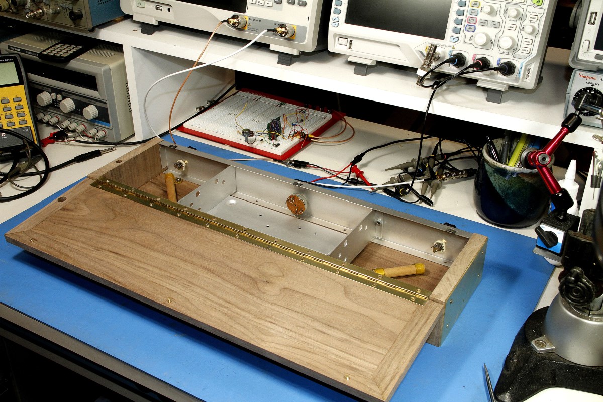
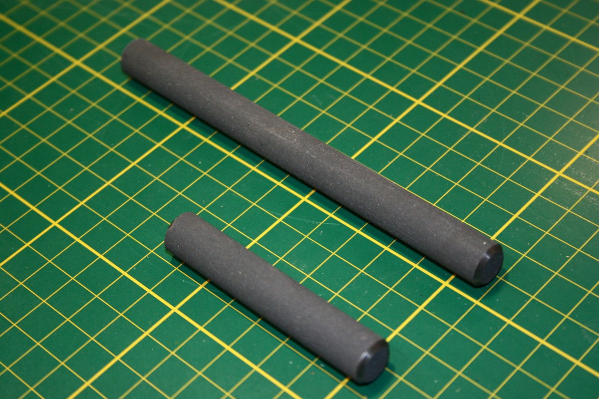
Replicating the Antenna Equalizing Inductors

I was able to buy 1/2" ferrite cores in 4" and 8" lengths.  These needed to be cut shorter for the Melodia, and for some reason I thought that the material would be easier to cut than it turned out to be.  On some smaller (and cheaper) rods I tried making dry-cuts with several different diamond wheels, but the material would chip terribly.  I finally read somewhere that heating would cause fracturing, so I dug out my tile wet-saw.  Even bathed in water the rod would randomly decide to fracture and ruin the cut.

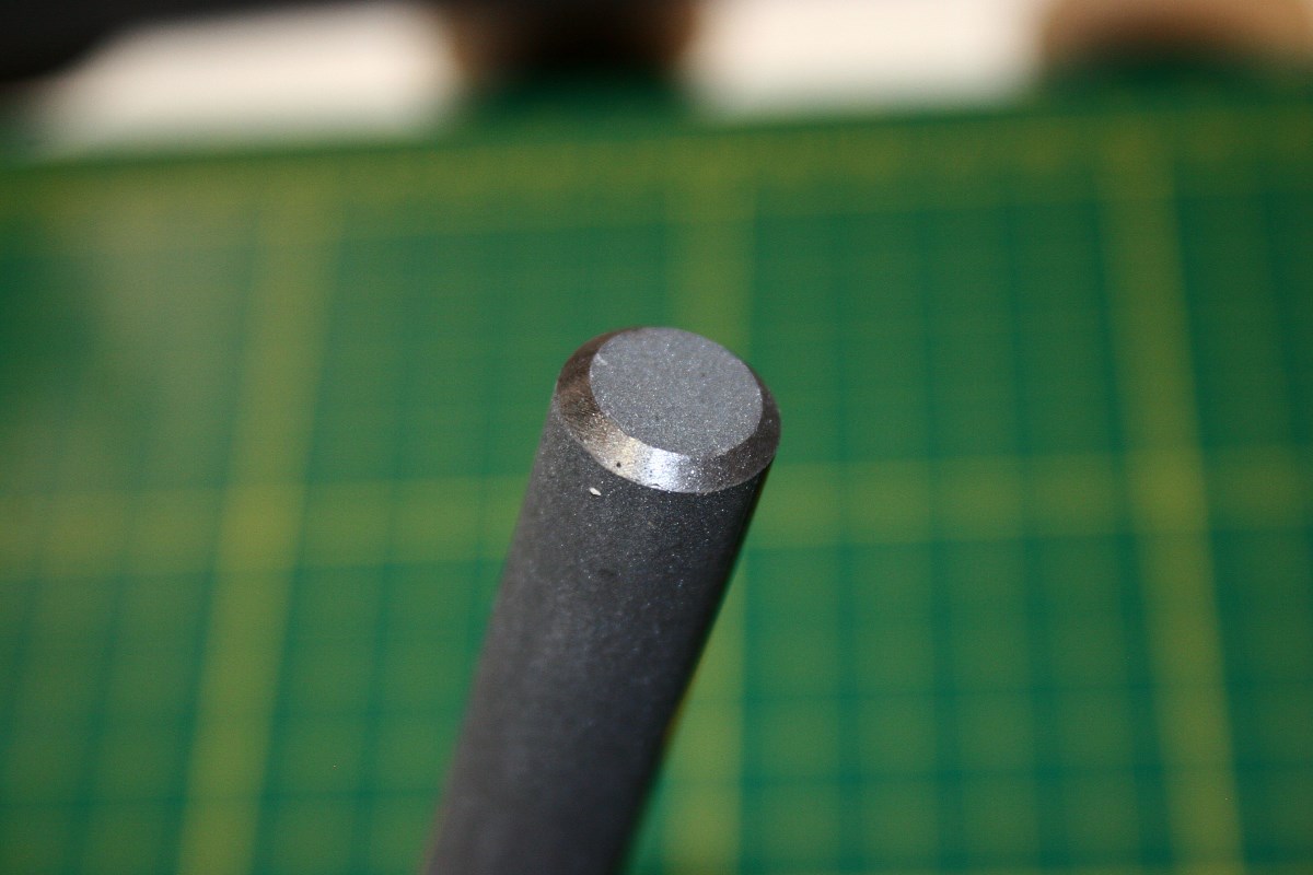
I finally made a wood support block with a 1/2" diameter cove routed into it to fully support the rod right up to the cut line.  Even with this the rod would chip around the cut line, but I went ahead and cut the rods close to length and end-ground them to final length.  Any remaining chipping was hidden by bevel-polishing the ends.  Whew - I'm glad that's done.


Winding the Inductors

This is probably going to be the biggest challenge of the project.  The goal here is to not only make a machine capable of replicating the simple "Universal" wind used on the four variable inductors/transformers (and the multi-section coils used in the Etherwave), but also one that is capable of applying the more complex "Progressive-Universal" winding used on the Melodia's large antenna inductors.

A universal coil winder would be easy to make in a few hours.  Dave Gingery wrote a booklet describing the construction of a winder that was essentially the same as the old Morris Coilmaster winder that was sold in the 1960s.

Morris Coilmaster:

A Gingery Version of the Coilmaster:

A core spindle is rotated while a wire guide moves laterally to wind the wire in a helix pattern, thereby minimizing inter-winding capacitance.  The lateral movement is not exactly synchronized in a 1:1 ratio to the spindle rotation in order to prevent the wire from winding directly on itself.  The Morris machine uses selectable gearing to lock spindle rotation to lateral movement;  the Gingery knock-off uses a continuously variable rubber-tire/disk transmission that also serves to provide the required right-angle translation without the need for bevel gears.

Both winders have a few points that could be improved upon.  It would be slightly better to have the spindle drive (which can slip under wire tension) linked directly to the crank handle, with the variable transmission driving the cam that provides the lateral movement.  Secondly, the lateral motion should ideally be linear, provided by a cardioid-shaped cam rather than a circular disk with an offset center.  And finally, introducing a pair of linked arms (adjustable) into the  fixed linear motion of the cam follower would provide a continuously adjustable lateral movement, allowing coils of different widths to be created without the need for using multiple interchangeable cams.

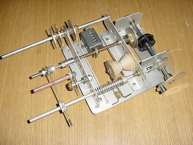
A Progressive-Universal winding machine is considerably more complex.  In addition to the fast cyclical lateral movement (on the order of the spindle rotation rate) of the wire guide, a slow lateral translation is introduced to shift the spindle continously as the helical windings accumulate.  This results in an inductor that can be thought of as similar to a multi-section pi-wound choke (such as the 3-section coils used in the Etherwave) except that the coil is wound continuously rather than separated into discrete sections. Here is a patent for such a machine (provided to me by a helpful contributor on the EEVBlog forum):


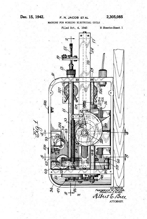
From what I can determine by reading the patent (always a joy...), the large central cam in the above picture is driven by a right-angle worm gear and provides the slow translation of the wire guide support arm. The faster lateral movement to create the helix wind is provided by the wire guide sliding within the support arm at a rate determined by an end-driven cam follower which is geared to the spindle rotation.

All in all this is an interesting but painfully complex machine to replicate, and one that requires multiple gearing and cam options to be versatile.

So what to do?

A simple mechanical helical Universal winding machine is easy to build, although an electronically programmable machine using a microcontroller and stepper motors may be just as easy for some.  But the introduction of the need for lateral translation to achieve a progressive-universal wind makes an electronic version the only practical choice.

So the options I am considering are as follows, and unfortunately none of these are quick or easy.  I don't like projects within projects, but from the start of the Melodia effort I was committed to making an effort to reasonable replicate the inductor windings as well.

Option 1
I have two metal lathe options - one medium-sized lathe that can provide a lead-screw translation motion geared to the spindle, and a small Taig lathe that can provide a slow open-loop translation that is not tied to the spindle.  For either of these lathes I could make a spindle encoder wheel to measure angular spindle rotation, and use a micro to convert this to drive an RC servo to shift a wire guide (for the helix wind), while letting the lathe's lead-screw provide the translation.  I don't think the translation needs to be locked to the spindle rotation unless you need to be able to stop and back up during the winding process.

Option 2
Make a dedicated dual stepper winder.  This would end up looking a little like a lathe (which is why I would like to leverage one that I already have).  The spindle however would be driven by one stepper, and the other stepper would drive a lead-screw on a linear table.  The lead screw would rotate back and forth quickly for the helical wind but increment the start and stop points to provide slow lateral movement as well.  The microcontroller would take care of everything.  This is conceptually ideal, but it involves both mechanics and programming, and then you would want a GUI interface, and so on.

Option 3
I have a newly built CNC milling machine that is nearly done except for some unresolved hardware/software bug that prevents completion of the control panel.  It has the option of adding a 4th axis for rotation.  This setup is tantalizing close to being able to provide x,y,z, and a-axis movement need to wind any coil scheme ever invented (well, maybe not toroids), all under G-code control.  But there is some work to be done to get to that point.

Option 4
Wimp out and make the simple mechanical universal winder, and use it to make a multi-section (like 20 sections) pi-wound coil.  It would wind coils that look slightly but not altogether different from the originals, and I have little doubt that it would work just fine.  Call it a Discrete Progressive Universal Winder.

Finally...

None of these options are quick and easy, so between this and the cabinet finishing experiments, and a few other interfering issues through the next two months there will be little progress on the Melodia for a while.  But stay tuned, and thanks for watching! 

Posted: 11/3/2018 4:40:14 PM
dewster

From: Northern NJ, USA

Joined: 2/17/2012

Roger, those are some really beautiful looking wood joints!  What's the electrical connection like for the pitch antenna?  Is there a larger diameter metal tube down in the hole or something?

"From what I can determine by reading the patent (always a joy...)"  - pitts8rh

Some of the most cryptic "explanations" on earth.  They claim the legalese is both necessary and precise, but I think there's usually a bad faith snow job working in there too.  They want something covered, but they don't want to tell anyone exactly what it is.  Every once in a while I run across a patent that's fairly straightforward / clear and it shocks me.

Is there any way to purchase one of those coil winders?  Short of that, I think I'd cobble something together that only does one kind of cross-wound donut, the one you need.  As in software, avoid solving the general problem when a specific solution will do.  That and I'm lazy! :-)  (That, and single layer air core solenoids have these beat hands down IMO, and are a cinch to wind, so for a non-historical build that's what I would pick.)  Do you have a need for various cross-wound ferrite chokes elsewhere?

Posted: 11/3/2018 5:18:21 PM
pitts8rh

From: Minnesota USA

Joined: 11/27/2015

Believe it or not, the pitch rod simply rests on a screw head, under its own weight.  The screw holds down a standard solder lug that extends into the case.

The Morris coil winders turn up from time to time on eBay and usually sell for about $50. They originally sold for something like $6.95 in 1967. They came with an assortment of gears and cams, so finding one that is complete is something to watch for. 

For me this is not about making something strictly functional, otherwise I would have taken other shortcuts.  I really want to try to replicate as much as I can, both functionally and visually.  Nevertheless, in the end I will be adjusting the inductances and antenna length to optimize the pitch field, after all I do want something playable and somewhat similar to my other theremins if that is possible.  I'm sure I could string together a bunch of Miller/Hammond inductors or something else to make it work, but I sort of like the challenge of doing it the hard way. Sometimes.

I do see a longer-term use for the basic universal winder and I will be building one of those anyway, but for a progressive winder (which may be for this project only), I have a problem putting too much effort into it and ideally I can adapt something that I already have.

Posted: 11/4/2018 8:58:51 PM
mpampouras

From: Lausanne, Switzerland

Joined: 3/15/2005

Wooow. That's an extremely beautiful built! Congrats!

Posted: 8/1/2019 10:28:14 AM
pitts8rh

From: Minnesota USA

Joined: 11/27/2015

Progress, Such As It Is

There haven't been any updates on the Moog Melodia project for quite a while, and although I've been doing a little bit of work here and there it has definitely taken a back burner to the D-Lev project.  Looking back I think I started the Melodia around the same time as the D-Lev prototype when I had a very different world view of theremins.  At that time I had several development boards in progress for enhancements to the Etherwave (with three full MAIN + CV board sets for putting together modified EW Plus theremins in new cabinets) and I had also tracked down a set of boards to build a Haible String Filter as an outboard processor for string effects.  But the D-Lev has turned out to be just about everything that I'll want or be able to handle in a theremin, so the rest of this work has been sidelined, probably forever.

My interest in the Melodia wasn't based on a quest for a better theremin, but more because it looked like a fun project.  A few genuine Moog Melodias have come and gone on eBay over the duration of the project, and for the time and money spent on this one it would have been more practical to just buy a real one even if I had to pay collectible prices.  But I wanted to build one more than I wanted to own one, if that makes any sense.  And since I try to finish all projects that I start (even if they get shelved for long periods) I finally made some time to complete a couple of small but significant tasks.

The cabinet was finished this last spring as soon as I was able to spray the lacquer outdoors.  After many color tests on walnut samples using aniline dye stains I came up with what I thought was a decent mixed and diluted shade of color to give the reddish hue that seems to be prevalent in so many photos of genuine Melodias.  But at the last minute I chickened out and simply sprayed Watco brushing lacquer onto the bare wood.  The color is missing warm hues and will fade over time, but it looks very similar to my walnut Etherwave.  And after looking at the photo below this may have been the right decision, because the walnut in the picture has a warmer color than I see in person, and the online photos that I had been studying may have displayed the same false red shift.  The same goes for the brown paint that I mixed for the panel.  This photo looks good, while the brown seems a little lighter in real life.

I wouldn't want to shoot a side-by-side comparison with a real one though...

The bigger milestone is the completion of the screen printed front panel.  I had finished the artwork for this last spring also, and in fact the screen was made in early summer and had been sitting around waiting for the big day.  The faint radial sector pattern that you see in the background is the remnant of a color wheel that was printed previously for a different project.


Screen printing, particularly in the DIY setting is very much suited to production runs where the start-up waste for prints is offset by the speed with which they can be mass produced once you get rolling. There are always wasted prints in the beginning until the whole screen is inked and flowing well, and it also takes a few passes to develop the squeegee technique for the particular project.  The problem here is that I had only one good panel to print, with one reject panel for practice, and I haven't printed anything for 20+ years.  If the print failed, it would not only mean stripping and repainting the brown paint on the panel but also cleaning the solvent-based ink out of the screen, stripping the photo emulsion, and redoing that as well.  It's much easier to screen print on items that are disposable (like paper) or can be easily wiped clean with solvent to reprint in the same session (things like unpainted or anodized metal panels for equipment).

With the screen all set up and inked I printed a few paper copies and then the reject metal panel, which turned out very well.  The real panel was then printed and came out with a slight shift on the right end, but I called it good enough.  The letters for the text came out a little fat, but this is very hard to judge when doing the artwork, and I was just happy to be done with it.

NOTE:  The lid in the picture below is resting closed and isn't screwed down, hence the gap above the panel.

The only major hurdle that remains is the machine-winding of the six inductors, and once these are finished the remainder of the project is going to be like building a Heathkit.  When I started this project I had planned to build a dedicated mechanical or stepper-motor universal/pi-coil winder to use for this and other theremin projects, but the D-Lev has ended any interest I had in doing other development.  Now I'm looking toward using a CNC milling machine as the primary x-axis positioner for coil-winding, with an added rotary stepper drive to coordinate the coil rotation with the x-axis shift.  I'm still not sure what I'll do here. This is all a little insane, but I have to finish it.

For now the Melodia looks nearly finished as long as I keep the lid closed.  I am looking forward to the final assembly and wiring. That should be the fun part.     

Posted: 8/2/2019 2:39:17 AM
tummosoft

Joined: 8/2/2019

That's an extremely trappy built! Congrats!

Posted: 8/4/2019 7:44:27 PM
mpampouras

From: Lausanne, Switzerland

Joined: 3/15/2005

Damn it's wonderful! Congrats!

You must be logged in to post a reply. Please log in or register for a new account.