(Yet another) Tube theremin project

Posted: 2/20/2019 3:39:31 AM
dewster

From: Northern NJ, USA

Joined: 2/17/2012

"If anyone has data on tank voltages & coil distance limits I'd love to compare notes."  - voretaq7

I did some testing a while back on two oscillators interacting, just to see what kind of frequency separation was necessary between the axes, not for heterodyning.  This stuff is very seat-of-the-pants, and in a perfect world gets nailed down early in the design (e.g. before a chassis gets picked out, punched, and populated - my usual sales pitch for ugly prototypes).  From my experiments and simulation even small differences in separation can give big changes in coil coupling if you want that to happen, but somewhat larger distances are required to make it minimal when you don't.  And as you note, tank voltage swing is likely a coupling factor as well.

Voltage regulation for each oscillator is critical for stability and isolation of solid state oscillators, not sure how this is handled in the tube world.  You seem to have a handle on the key things to investigate though.  Good luck and godspeed!

Posted: 2/20/2019 6:54:33 PM
Henk Brand

From: Schiedam The Netherlands

Joined: 12/22/2014

Although not the same oscillators you can see on my foto’s on page 3 of the photoalbums ( Clara Rockmore replica)  how I placed the coils beneath the chassis. I agree with Dewster that voltage regulation is important, that’s why I use tube voltage regulation with EL84 for the 90 Volt plate voltage of the oscillators. B.t.w. these Lev. Oscillators work just as good with ECC82 (12AU7) ;tubes as with the original 27 tubes but you have to combine the plates, grids and cathodes together to let the tube handle more current.
With 90 Volt plate voltage the tubes draw some 10 mA current. They are working now for three years without  any troubles.
The coils are the standard coils as used in the RCA theremin because I couldn’t find details of the coils used in the original Clara Rockmore Theremin but the pictures I saw suggest the same values. The pitch part of the Clara Rockmore was not the biggest problem in building but the volume part was. After I found out that the coupling coil was not placed over the volume coil but underneath it, I made a moveble coil with several taps so I could tune it for optimal working. If you look at the pictures of the coupling coil I have several taps and it turned out that tap 3 worked best for me. Of course the magic of the Clara Rockmore theremin is the modulation in the 24 tube together with the interstage transformers. Although my replica works just fine, I’ve heard that there are some mistakes in the schematic which was traced out by Robert Moog. So sometime in future I hope to hear from Mike and Andy what these mistakes were so I can optimise things.
I follow your posts with great interest and I hope you will succeed in building another great tube theremin. After all there is nothing more pleasing then playing your own built theremin be it a tube transistor or digital one.     

Posted: 2/20/2019 9:52:02 PM
voretaq7

Joined: 11/13/2018

So rather counterintuitively stepping down the power last night caused the oscillators to lock in sync earlier (around 1KHz). I suspect this is because they ARE RF coupling at the coils & with less of a "kick" in the tank it's easier for them to pull into sync. This tracks with the fact that I get strong oscillation in the variable oscillator's tank if I power that oscillator off and tune the trimmer capacitor so the tank matches the reference oscillator's frequency. (The beat frequency also seems to be getting superimposed on the variable oscillator, which probably shouldn't be happening & is again maybe due to over-coupling and that oscillator having a "weaker" tube in it - that tube has been through some abuse & barely tests within spec anymore. Now that the smoke debugging is done it may be time to break out some factory-new parts.)

This also means shielding might be effective. Sadly I had no foil around to try so I'll have to pick that up on the way home tonight. If that doesn't work I'll redo my alligator-clip wiring & try to fix the problem with distance.


Ultimately I may be suffering from my own cleverness in making the oscillator tanks 8-pin "plug-in" modules since that means I can't reorient them (all 3 are forced to be oriented at 90 degrees to the chassis, parallel with each other and with the tubes). If that layout constraint turns out to be problematic I'll fall back to Lev-style independently mounted coils bolted under the chassis with screw/spade terminals to connect them. Not a major hardship since I'm 3D printing the forms & can change the design, but it would make the chassis less self-contained than I had hoped.


As a note the test oscillator tubes are ECC83/12AX7s since that's what I have laying around - functionally they're similar to what Henk described, both sections paralleled so they can pull decent current (5mA in this case, with the tube max being around 12 in parallel). The most substantial difference is I used a Hartley oscillator instead of Lev's Armstrong oscillators as it's easier for me to wind a single layer with taps than 2 layers.
Since reducing the oscillator power caused them to lock sooner ECC82/12AU7 tubes may be better in this application (more current draw means more "kick" in the cathode part of the coil which may reinforce the local oscillator's frequency over the external influence of its partner).

Posted: 2/21/2019 2:46:04 AM
voretaq7

Joined: 11/13/2018

Update: As usual shielding makes the RF world go round: With a sheet of foil taped between the two oscillators I have been able to get far more desirable results:

(I can probably get a bit lower than 73Hz but things are currently precariously balanced upside-down on my bench so I didn't really try tweaking more once I got myself safely into "Guitar Range".)

Pulling the foil promptly returns the oscillators to their over-coupled state, and obviously when the foil moves the oscillators get perturbed (capacitance changes between the shield & the coils) so I guess it's time to measure and build appropriate shields.

A note about the waveform: This is tapping the oscillators off their grids & using the scope's "ADD" button - It's very raw, and the final waveforms may wind up looking different after the mixer tube has its way with the signal.

Posted: 2/24/2019 8:54:12 AM
voretaq7

Joined: 11/13/2018

Aside from being a total nightmare of wires flying everywhere still (waiting on some RF chokes to try in place of the massive wirewound resistors for power supply decoupling before I start soldering the guts) the pitch section has come mostly to life - I have not yet wound a coil for / connected a proper pitch antenna, but by varying the oscillator tuning I'm able to manually sweep the frequency, and the oscillators respond to my hand's proximity in a decidedly theremin-like fashion.

The two issues I've got at the moment are both related to the EF86 I'm using as a mixer tube.

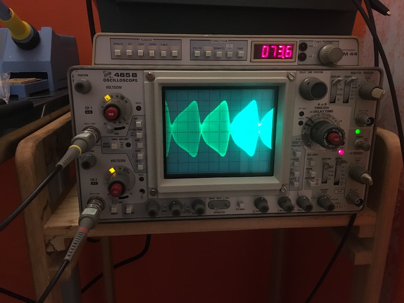
The first issue is that the tube is is biased into cutoff by the negative voltage swings (flat upper peaks on the scope as the output hits the power supply voltage). This may not actually be a problem: Per at least one source (https://www.thereminvox.com/article/articleview/28/1/2/index.html apparently taken from Moog's notes) the Rockmore theremin behaved similarly, though as we have no waveform data from that unit as far as I know it's hard to determine if this is entirely correct. Henk's construction photos include waveforms and mine are broadly similar (I expect the differences are probably due to the lack of a coupling capacitor, and also my tapping off the grids of my oscillator tubes to feed my mixer which is convenient but probably not optimal).

The second issue is that my waveform is "fuzzy" at its peaks: RF is bleeding through from the previous stages.  I suspect this one is related to the fixed resistance I currently have in series with the control grid (G1) of the EF86 (15K Ohm - closest loose resistor to the RCA Standard 10K I had laying around without busting open a bag) and the lack of any resistance in series with the screen grid (G2) - prior to adding the resistor to G1 the entire waveform was a fuzzy mess of aliasing because the signals weren't balanced (G1's RF component was swamping the audio-frequency output). Some experimentation and two potentiometers as in the Rockmore theremin design should allow me to clean this up by matching the input waveform magnitudes.


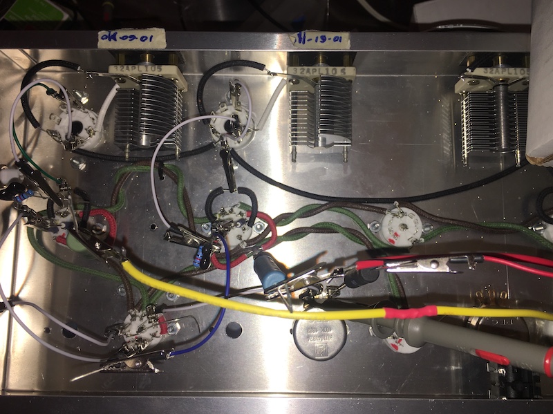
Obligatory disaster porn - The current state of the alligator clips and jumper wire internals:


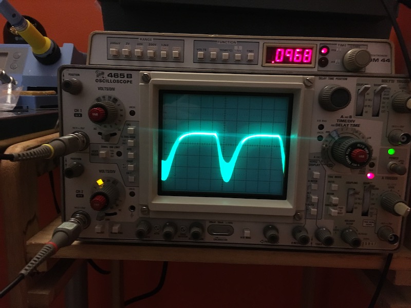
and the current output of the mixer tube (96.8Hz):

Not pictured: The new shield plates on the top side of the chassis (because if I flip the stupid thing over right now parts will start falling out), but if you follow the mounting screws from the variable pitch oscillator's tuning capacitor (top left) toward the mixer tube (bottom left) you'll see two screws almost in line wtih that socket's mounting screws. That's the back of the shields, and the front is attached to the capacitor mounting screws.
Two shields are employed to balance the capacitive effect on the oscillator coils & keep the zero-beat point for the pitch oscillators close to center on both trim capacitors.

Obligatory Safety Warning:
In these photos you've seen me put 300 volts at half an amp through precariously balanced resistors and alligator clips sticking out of an open chassis like the quills of an electrified porcupine waiting to arc and short at the slightest breeze. As a result there is a not-insignificant risk I will fry components, start a fire, or even kill myself. I am a dangerous idiot, and you should employ better electrical safety practices when prototyping equipment.

Don't be like me - it's a miracle I've lived as long as I have.

Posted: 3/5/2019 7:36:14 AM
voretaq7

Joined: 11/13/2018

Update update update update (MUSHROOM! MUSHROOM!)

So the pitch section is probably done - It heterodynes, it tunes (sub-40Hz to squeaky annoying), and it plays through my little practice amp. As with any musical instrument hearing is believing - I'll probably assemble more sound samples as things get closer to completion but here's one of the test tones. (I've noticed a lot of sound samples are done by playing full musical compositions & once I have the basic unit assembled with antennas and coils I may try my hand at those, but for now selected notes seems like a better way to evaluate the instrument's tone.)

Coupling capacitance between the two pitch oscillators is proving unnecessary even with my shielding in place: Any added coupling, even as little as 1.5pF, creates a very sawtooth-type wave and buzzy tone I'm not personally happy with, and I find a more pleasant variant of that same buzzy tone can be approximated by cranking the grid resistance on the mixer tube all the way down and allowing the two oscillators to pull toward each other that way - lots of harmonics start poking out of the waveform if you let them.

The next element to work out is the volume control which I expect to be the more difficult of the two: The ingenious solution of using RF to provide filament voltage is somewhat less practical with modern tubes so I get to start trying to figure out how that should all work with a screen-grid VCA.

You must be logged in to post a reply. Please log in or register for a new account.