Teensy 4.0 600MHz ARM Cortex M-7 MCU - ideal for digital MCU based theremin?

Posted: 10/22/2020 6:27:15 PM
Buggins

From: Porto, Portugal

Joined: 3/16/2017

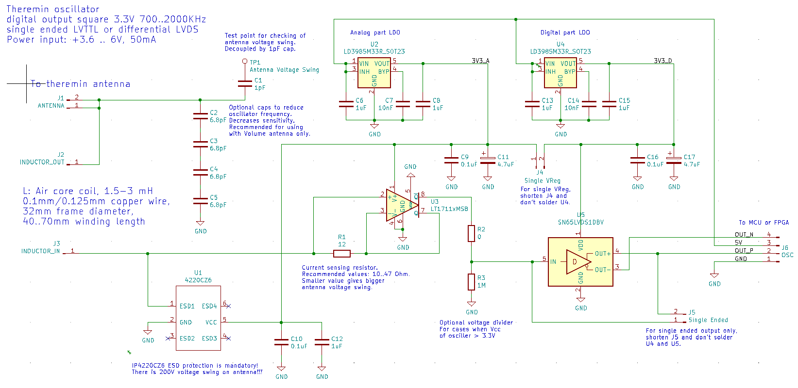
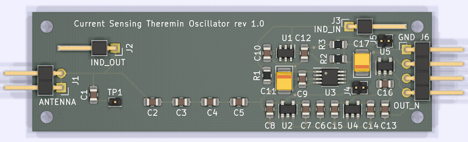
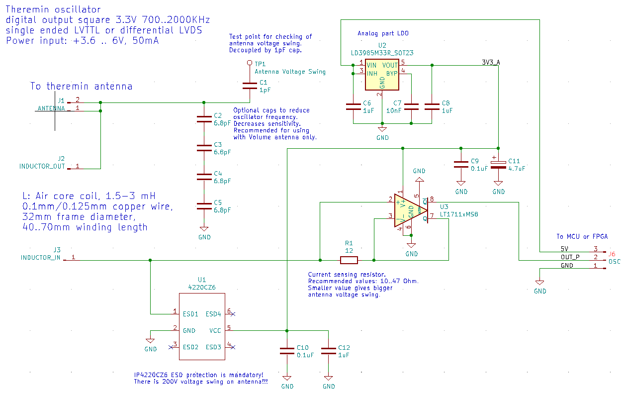
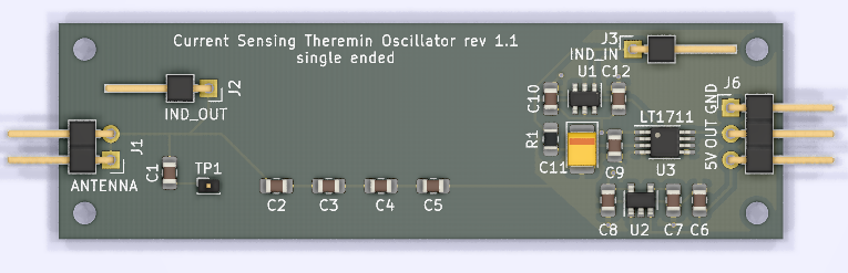
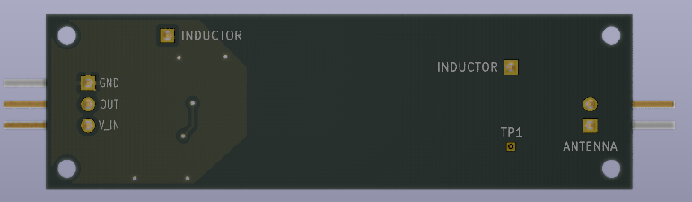
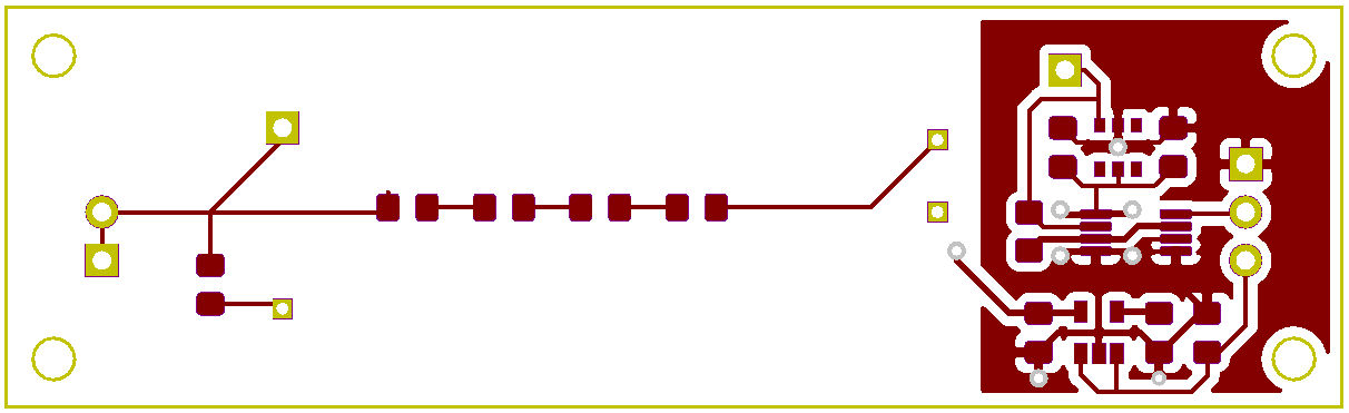
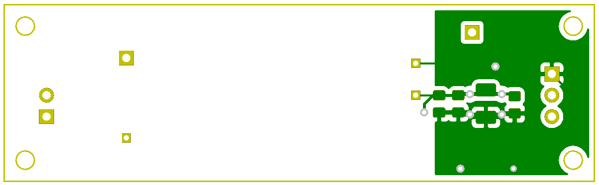
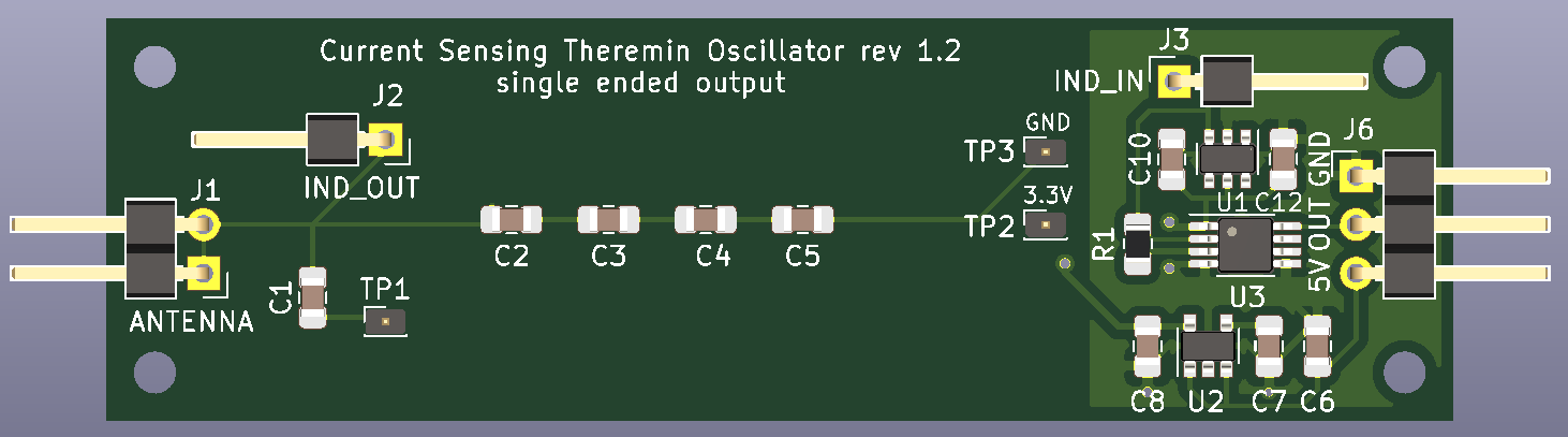
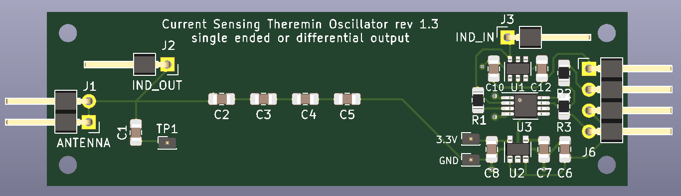
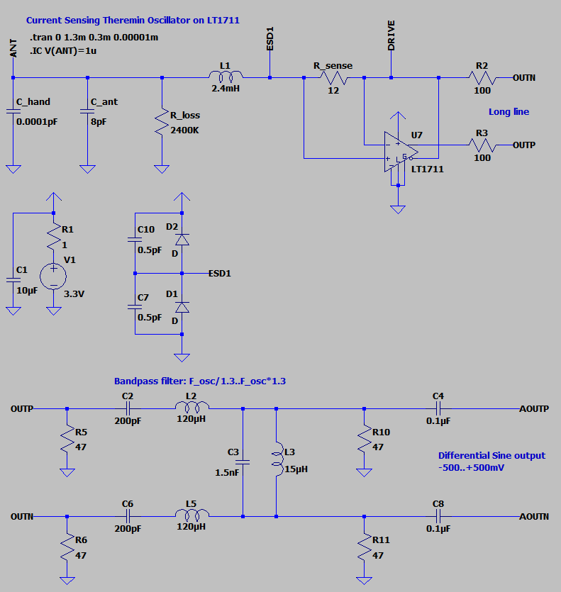
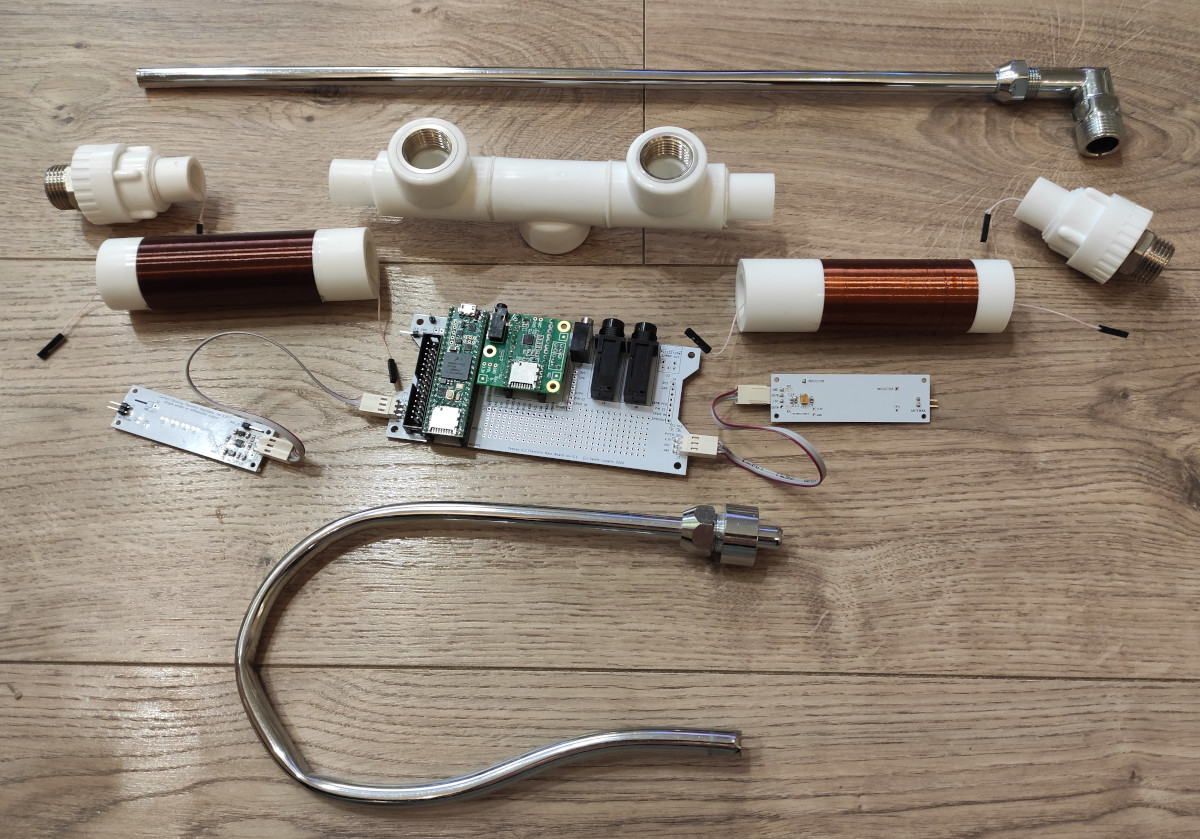
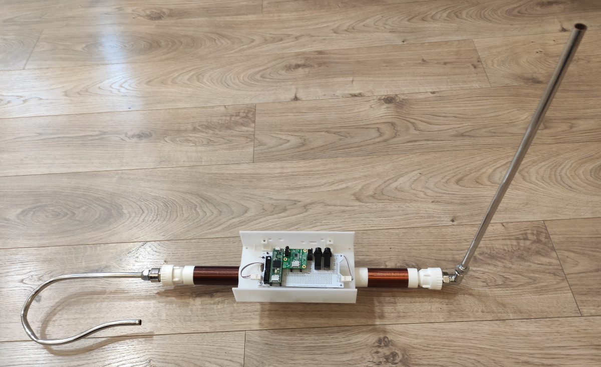
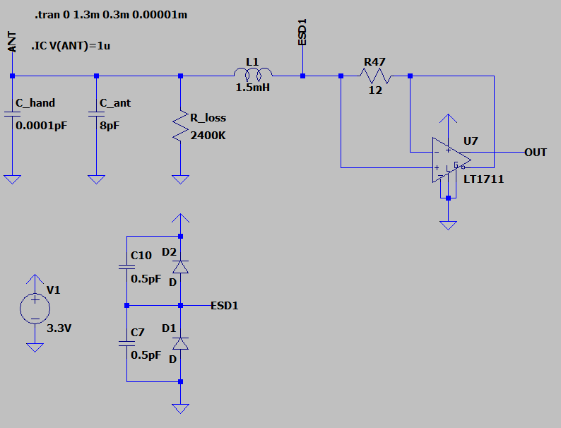
Building simplified version of dewster's current sensing oscillator from Analog Theremin thread post

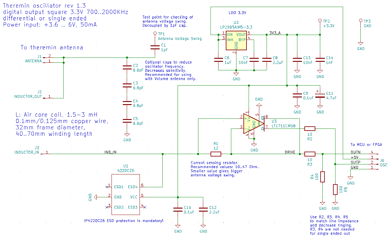
Tried to play with current sensing resistor based oscillator approach in ltspice.

Even managed to get working differential BJT cascade in LTSpice.

Finally found working comparator which can sense current of resistor on its own output. At least it's oscillates in model.

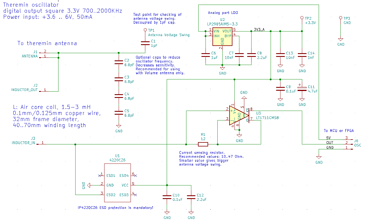
All you need for oscillator are 2 components: LT1711 and resistor.
Of course, I forgot antenna and inductor.

Simulation results in LTSpice: 1400Vpp antenna swing


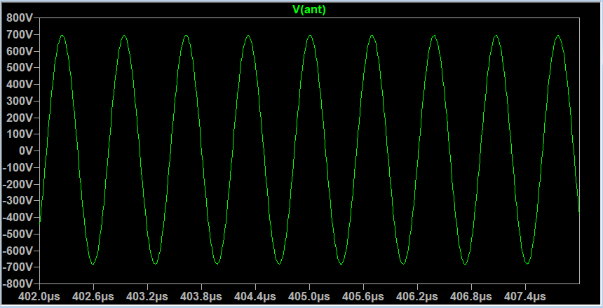
It was 12V power (max supported by LT1711)

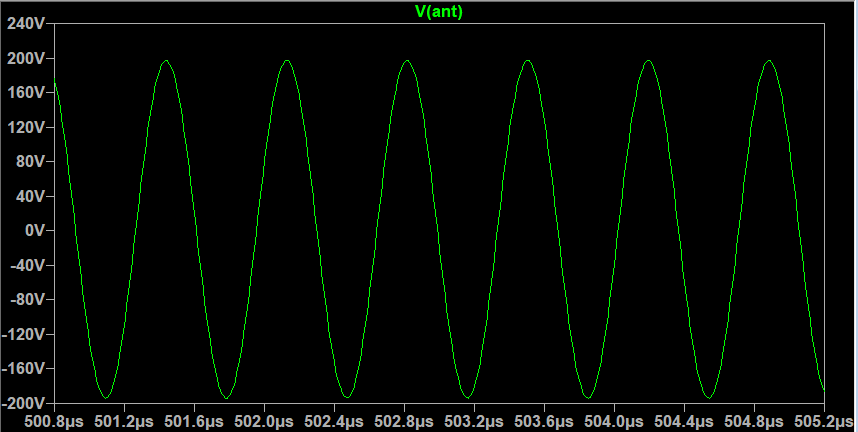
Here is the same circuit powered from 3.3V: 400V antenna swing (with high R_serial inductor, can drop to 250Vpp)


LTSpice model:


Download link


Sensitivity (change of frequency for C_hand 0..1.5pF) (1452KHz-1332KHz)/1452KHz = 8.26%

BTW, it looks like LT1711 model pins are wrong. Lower pin which is drawn as inverse, is actually positive.

Second output pin can be used as digital output.

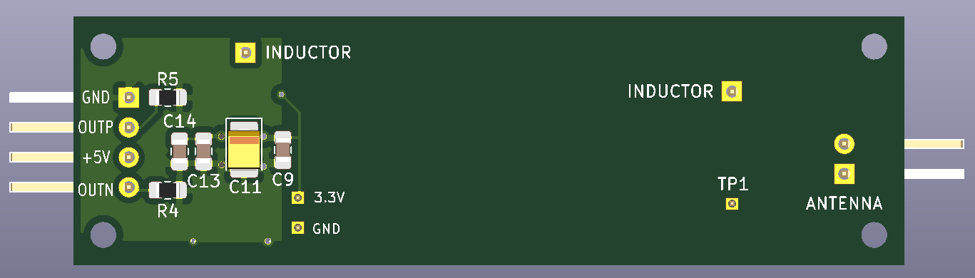
For clean sine wave, simple LC filter can be added.

According to simulation, this schematic is resistant to hand touches - even w/o decoupling cap suggested by Thierry.
With C_hand = 150pF antenna swing just drops down to 60Vpp (to 400Vpp when powered with 12V).

BTW, is it safe touching antenna with 1400Vpp? 

Supply current is 35mA 12V when touching antenna, inductor current is 50mA.

For 3.3V, supply current is 17mA.

Posted: 10/22/2020 10:11:43 PM
dewster

From: Northern NJ, USA

Joined: 2/17/2012

"According to simulation, this schematic is resistant to hand touches - even w/o decoupling cap suggested by Thierry.
With C_hand = 150pF antenna swing just drops down to 60Vpp (to 400Vpp when powered with 12V)."  - Buggins

Yes, in simulation you can put 25k to ground and it still oscillates, even without the 150pF.  Quite impressive!

"BTW, is it safe touching antenna with 1400Vpp?"

Dude, you're building a Tesla Coil! ;-)  Could probably light a fluorescent tube with that...

"For 3.3V, supply current is 17mA."

It seems quiescent for the comparator @ 3.3V is around 14mA.  This is a $6 part, kinda expensive and specialized, but it certainly seems to do the job. 

By using an NPN / PNP output buffer you might be able to use a device with lower output current, and the inputs would stay at least one diode drop away from the rails so you wouldn't need rail-to-rail inputs.  Plenty of antenna voltage swing to spare here so lowering the drive voltage wouldn't hurt.

Don't you have a little Thereminist you should be looking after? :-)

[EDIT] Just tried a buffer in simulation, seems bad.

Can't beat this circuit for simplicity, swing voltage, and sensitivity - I wonder how stable it is?

Posted: 10/23/2020 5:40:36 AM
Buggins

From: Porto, Portugal

Joined: 3/16/2017


It seems quiescent for the comparator @ 3.3V is around 14mA.  This is a $6 part, kinda expensive and specialized, but it certainly seems to do the job. 

$6*2 component price is not a big deal comparing to other components (MCU/FPGA, encoders, etc).

I've checked power consumption of circuit in LTSpice.
Tried R_sense 10 to 47 Ohm, added 150pF C_Hand + 150K R_loss - current from regulator should under 17mA.

BTW, in LT1711 datasheet, there is a special chapter which describes how to force it not to oscillate


What R_sense to use?

Antenna voltage swing dependency on R_sense:


Code:
R_sense   V(ant)
-------   --------------
8         no oscillation
10        300Vpp
12        290Vpp
15        285Vpp
20        281Vpp
50        252Vpp
100       216Vpp

Checking FFT of signal on antenna - difference between signal and flat area at lower frequencies - for different window types


Code:
R_sense   no window   hamming   blackman
-------   ---------   -------   --------
100       67.9dB      87.1dB    113dB
 10       72.4dB      91dB      118.4dB

It looks like lower R_sense gives 5dB better sine. Signal/noise ratio should be better (300V vs 216V).
So it makes sense to choose low R_sense value - maybe, 10 or 12


Let's imagine that we have pretty good signal on output of sensor.
But it can be damaged on the path to MCU or FPGA. I'm planning to use twisted pair cable with length of 15-20cm to connect oscillator board to main board.
Sharp edge requires terminating resistors to keep waveform shape good enough.
High current in line with terminating resistor(s) as well reduces influence of noise.
The best way imho is to use differential signal for transmission - e.g. standard LVDS.
SN65LVDS1 and SN65LVDT2 can do this work.
Receiver part may be not needed if FPGA supports LVDS input on pair of pins.


Don't you have a little Thereminist you should be looking after? :-)

According to current progress in my project, little Thereminist will graduate the school by time I would finish my construction


Posted: 10/23/2020 1:27:23 PM
dewster

From: Northern NJ, USA

Joined: 2/17/2012

"What R_sense to use?"  - Buggins

Higher R increases the "gain" of the resistor in converting current to voltage (V=I*R) so the larger the better for intrinsic noise and stability.  On the other hand, R decreases Q so the smaller the better.  We've seen that coil DCR isn't that big of a player when it comes to Q, so I'd say the first more or less trumps the second (within reason) and we're looking for a happy medium.

It really comes down to stability though.  If a small R doesn't give good stability, or otherwise exposes the noise in the gain, then you can't use it.

I'm looking at the circuit running on my bench again.  I hooked a more normal sized rod antenna to it and set it on a larger plastic box.  It's remarkably stable, and easily "sees" my open and closed hand from >1m away (~1 cycle @ 778kHz delayed 1/60Hz).  If you can breadboard it or build it on vector board you might want to give it a spin.  The antenna rod that I'm using is insulated with heatshrink, and I can lightly touch it with one fingertip without oscillation totally dying.  There doesn't seem to be any issue with starting / restarting.  If I'd found this oscillator earlier on I might have gone with it (I actually did find it earlier on via hacky CMOS, but never thought of trying a discrete NPN approach until now).

Posted: 10/23/2020 6:03:51 PM
Buggins

From: Porto, Portugal

Joined: 3/16/2017

I'm looking at the circuit running on my bench again.  I hooked a more normal sized rod antenna to it and set it on a larger plastic box.  It's remarkably stable, and easily "sees" my open and closed hand from >1m away (~1 cycle @ 778kHz delayed 1/60Hz).  If you can breadboard it or build it on vector board you might want to give it a spin.  The antenna rod that I'm using is insulated with heatshrink, and I can lightly touch it with one fingertip without oscillation totally dying.  There doesn't seem to be any issue with starting / restarting.  If I'd found this oscillator earlier on I might have gone with it (I actually did find it earlier on via hacky CMOS, but never thought of trying a discrete NPN approach until now).

Glad to hear it.
I hope LT1711 oscillator will be even more stable than your BJT.

So far, I routed PCB for LT1711 oscillator experiments. Going to order and wait for one month (slow delivery).


It's a bit overcomplicated but allows to test a lot of options.
Optional LVDS output - don't solder and shorten J5 if not needed.
Optional higher Vcc for comparator (used only with LVDS output). When used - solder R2, R3 to divide voltage to 3.3V. If not used, R2 should be shortened.
Optional separate regulators - for oscillator and output. Mandatory when using higher voltage. Optional when oscillator is powered by 3.3V. Only one reg is needed for single ended output.
Some caps may be not soldered.
Optional capacitor chain from antenna to ground (e.g. to reduce frequency of volume antenna w/o big L).
Optional 1pF decoupling capacitor to measure antenna voltage swing.


PCB render top view:


PCB render bottom view:

Strange PCB layout - because it's intended to fit into 32mm plastic water pipe - frame of inductor. For out-of-tube usage, just solder vertical pin headers to use screw holes.


KiCAD project shared on github


Gerber files download link

Simplified design - single ended output.


KiCAD project on github

Gerber files download link

Posted: 10/24/2020 6:39:36 AM
Buggins

From: Porto, Portugal

Joined: 3/16/2017

Updated single ended output pcb.

Trying more compact layout, with bypass caps on bottom side.
Double vias of bigger size for both gnd and 3.3v from top layer comparator power pins to bottom layer bypass caps.
Added 1nF and 10nF optional bypass caps.
Traces for comparator are wider now.
Added 3.3V and GND test points.


KiCAD project on github

Gerber files download link


Posted: 10/24/2020 8:19:43 PM
Buggins

From: Porto, Portugal

Joined: 3/16/2017

Ordered PCBs for last published design of oscillator.
Unfortunately, it will took up to month to receive them.

Posted: 10/30/2020 8:03:51 PM
Buggins

From: Porto, Portugal

Joined: 3/16/2017

Good news: I've received main board and display/controls boards for Teensy4.1 theremin.

On photo, there are boards together with main components: Teensy 4.1 MCU, audio board and touch LCD.

Display/controls board is a bit strange. Wrong footprints for pots: mounting holes are not drilled. This footprint is from standard KiCAD collection of footprints.
LCD mounting holes are not drilled as well. Not sure why. Probably, display footprint I made is incorrect.

Waiting for components I've ordered to solder the boards.

Bad news:

Unfortunately, I've found bug in previous revision of PCB: when positive input is after R_sense, and negative is before R_sense,
L should be driven by negative output of comparator. In revision 1.2, it's fed by positive output. So, PCBs which are manufactured and in delivery cannot be used unless track from positive output is cut and negative one is soldered as inductor drive instead.

Designed and ordered new version (rev 1.3) today.

KiCAD schematics:


Differential output mode is now available. For single ended output mode, 3-pin connector with the same pinout as in previous version can be soldered.
For both outputs resistors are routed. Serial, pulldown or both resistors can be used to match line impedance.
When output resistors not used, serial resistors can be replaced with wires.

PCB:


Sample usage of oscillator differential output with filter for ADC (+-500mV, sine with -45dB 3rd harmonic).

Suitable for feeding of 100MHz 8bit ADC AD9283BRSZ-100 for FPGA based implementation I want to try.

Model file link

Posted: 12/9/2020 7:08:22 PM
Buggins

From: Porto, Portugal

Joined: 3/16/2017

Soldered LT1711 current sensing oscillators, and got first test results.

Test setup:

Volume inductor: 4.485mH 133.5 Ohm 0.1mm wire 77mm winding length on 32mm polypropylene frame
Pitch inductor: 2.624mH 66 Ohm 0.125mm wire 66mm winding length on 32mm polypropylene frame

LT1711 based inductors with 22 Ohm R_sense.

Pipe monster design parts:


Assembled:


Mounted part of cabinet from old teensy theremin project.


Oscillators are working. Sensitivity is good.
Oscillation is unstable with 22 Ohm R_sense, with small (pitch) inductor. Works much better with bigger R_sense.

Problem: on antenna touch, oscillator goes to high frequency oscillation (3-10MHz) often not recovered after removing of hand.
Tried to change R_sense to 100, 220, 1000 Ohm - no effect.

Dewster, does your bipolar differential schematic work ok when antenna is touched?


Posted: 12/9/2020 7:41:37 PM
pitts8rh

From: Minnesota USA

Joined: 11/27/2015

Just a side note...  

If you would like to smoothly bend copper tubing for your volume loops, crimp or cap one end of the straight tube and solder it shut.  Fill it with water and crimp or cap the top end with a small air space, and solder it shut too.  Then freeze the tube vertically or at least with enough slope to keep the air at one end.

When it comes out of the freezer bend it immediately around a form or anything cylindrical.  It will bend smoothly like a solid rod without kinking, although be prepared to use a little more bending force as you might expect.  Then just cut the ends off and drain the water.  Works great!

You must be logged in to post a reply. Please log in or register for a new account.