Buchla Model 117 Proximity Detector

Posted: 5/9/2020 11:44:16 AM
apetechnology

Joined: 5/5/2020

For a couple years I have been working on replicating and studying Buchla modular electronic instruments with a colleague at University of Michigan. We have thoroughly built and studied multiple modules from this system, however one specific schematic has us a bit perplexed. I was wondering if I could pick the collective brains of Theremin World since RF and theremin circuits are not an area we have much experience in.

Attached is the only scan of the schematic we have:

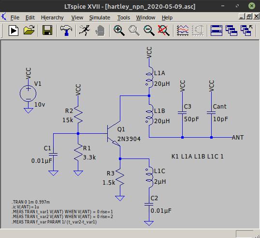
The 117 Proximity Detector is a module that has two detachable antennas so the performer can use both hands to adjust frequency of two separate oscillators. It would appear that this circuit is using the Hartley oscillator as the basic building block for both the primary and secondary oscillator. The problem is, the schematic does not clarify much about the coils used. I have spoken to a synthesizer tech about this, and even after trying some of his suggestions, we have not made much headway. 

Our tech friend suggested that the coil shown in each oscillator is a tapped coil that is possibly coupled between the emitter circuit of the hartley and the collector, so he made a part suggestion. The coil we ended up using was a Coilcraft SWB-2010-1-PCL, datasheet located here:

https://www.mouser.com/datasheet/2/597/swb-1223867.pdf

It would be noted that one aspect of the project we are working on is keeping things as original as possible so we can study the module fully as it would have been in 1969, so we don't need a polished circuit, but one that works... I think there is an issue with the coil we used - can anyone kindly take a look at this circuit and see if there are any issues that we might be missing?

Posted: 5/9/2020 4:06:53 PM
oldtemecula

From: 60 Miles North of San Diego, CA

Joined: 10/1/2014


IMHO - This project is a rabbit hole, I say that politely as others are more experienced in exploring them and I will let them take you home.


Posted: 5/9/2020 4:37:23 PM
dewster

From: Northern NJ, USA

Joined: 2/17/2012

"Our tech friend suggested that the coil shown in each oscillator is a tapped coil that is possibly coupled between the emitter circuit of the hartley and the collector"  - apetechnology

That could be the case, otherwise I don't see how the LC tank might be providing feedback.  I would try isolating the oscillator circuit on a breadboard (use every other hole to minimize stray C, and place it on a plastic box - don't use the type that has a metal base plate) to just Q1 and surrounding passives, and hand winding coils with various tap points on a small piece of ferrite until it starts to work (or not, as the case may be).  Not knowing the details of the coil - particularly when there are taps and coupling going on - can be quite crippling.  Have you got it to oscillate at all?  Thanks for sharing the schematic!

"What I see is two RF oscillators and an audio amplifier section..."  - oldtemecula

I believe I understand the rest of the circuit, and there's more going on than that.  Take your Phoenix ads elsewhere please.

Posted: 5/9/2020 5:23:20 PM
apetechnology

Joined: 5/5/2020

"Have you got it to oscillate at all?"

We have achieved oscillation but it's far from a perfect sine, and nowhere near 2 MHz. We get a waveform like this, that decreases in amplitude when we move our hand closer to the "probe". The probe we are using is a flat piece of copper clad, and we have it isolated from our work environment. I'm definitely thinking we have a problem with the coil as suggested - as it's the only real unknown here on the schematic.

Buchla was notorious for schematic errors but we have never had a circuit that just refused to cooperate. I've tried changing the tank capacitors as per another suggestion with no positive results.

Posted: 5/9/2020 5:47:42 PM
dewster

From: Northern NJ, USA

Joined: 2/17/2012

"We have achieved oscillation but it's far from a perfect sine, and nowhere near 2 MHz."  - apetechnology

Ha!  So that's what that weird 'P' combined with an 'L' is: 2!  And "mc" is megacycles, or MHz.

"We get a waveform like this, that decreases in amplitude when we move our hand closer to the "probe"."

It's normal for Theremin oscillator amplitude to reduce as the hand approaches (I believe this is due to human body resistance damping the oscillation).  But that amplitude is pretty small, not to mention gnarly looking.  100uH coupled with 50pF does give ~2MHz as resonance.  I assume you've tried swapping the polarity of the sense coil winding?

Since the circuit uses a variable C to tune the fixed oscillator, if you can't get it to work with the specified oscillator topology, then you might try another which employs a simpler inductor arrangement.

Posted: 5/9/2020 5:59:12 PM
apetechnology

Joined: 5/5/2020

"Ha!  So that's what that weird 'P' combined with an 'L' is: 2!  And "mc" is megacycles, or MHz."

Haha, Don was always fighting the standards, too cool to pander to Heinrich Hertz... Yes, the venerable upside down 5... so many hours lost misreading the schematics...

We haven't attempted reversing the polarity of the sense coil... But would be easy enough to do. I'll see if that makes any difference.

Posted: 5/9/2020 6:04:19 PM
JPascal

From: Berlin Germany

Joined: 4/27/2016

Apetechnology, can you tell us where the time signal is measured? This could be a phase shifted rectangular wave form. If you take a small coil connected with the oscilloscope-probe and bring it in the field arround the oscillator, there should be a sinus be obtained?

Posted: 5/9/2020 6:24:43 PM
apetechnology

Joined: 5/5/2020

Apetechnology, can you tell us where the time signal is measured? This could be a phase shifted rectangular wave form. If you take a small coil connected with the oscilloscope-probe and bring it in the field arround the oscillator, there should be a sinus be obtained?

hello JPASCAL,

The signal shown is from the right side of c22 on the bottom schematic, the "probe" schematic.
this is a general question for this forum, what size ferrite should i have for experiments? and also what gauge wire/type.
thank you for everyones help so far! looking forward to getting this old beast going!

Posted: 5/9/2020 8:10:36 PM
dewster

From: Northern NJ, USA

Joined: 2/17/2012

I spiced it [LINK]:

I changed the inductances until it oscillated at ~2MHz, these values are probably heavily influenced by the coupling of the coils, which I've got set to 1. 

It won't oscillate with the wrong polarity, nor with 1:1 inductances, so I think you need a different transformer.  I'd go for a step down transformer, with taps on both sides so I could experiment with the ratio.

When it does oscillate, the antenna voltage swing (in simulation) is quite healthy: +45V / -12V (with 10V VCC) though non-sinusoidal.  I should have put a 1M resistor from ANT to ground to simulate RF losses (I just did this: no real reduction in antenna swing).

The sim was taking forever and crapping out until I gave the inductances small DCR (series resistance) values of 0.2 Ohms.  View the spice error log for the frequency measurement.

Posted: 5/10/2020 6:49:56 PM
apetechnology

Joined: 5/5/2020

Thanks so much for your work on this dewster, this is amazing information. Now we have at least the inductances needed to get the thing to oscillate.

I'm pretty well prepared to find zero off the shelf transformers that will work properly, so I probably need to start winding my own. I was considering winding a toroidal transformer to do the trick. Do you have any suggestions on where to start? I've wound guitar pickups before but never a transformer.

I can totally see the response curves of this thing as nonstandard for theremins of the time, we have no idea what Don had intended this circuit for (it was purportedly used for a specific performance), so we do not know where the antennas were installed or how much range of movement he had in mind. This was strictly a one off module that is lost to time.

I'll get to work on trying out some solutions... if you have any other suggestions or any idea of parts that would fit the bill, I would appreciate it!

You must be logged in to post a reply. Please log in or register for a new account.