Buchla Model 117 Proximity Detector

Posted: 5/10/2020 8:03:24 PM
ILYA

From: Theremin Motherland

Joined: 11/13/2005

"I was considering winding a toroidal transformer" -- apetechnology

40 uH is not the case when ferrite is required.

Moreover,  ferrite should be avoided, since its properties depend on temperature very much. The greater the permeability, the stronger the dependence. Lack of gaps (as in torroids) also increases the dependence.

Posted: 5/10/2020 8:24:03 PM
dewster

From: Northern NJ, USA

Joined: 2/17/2012

ILYA, the windings need to be highly coupled, so I think something like an IF transformer with weak gapped ferrite is probably called for?  The type of RF transformer they picked might work if the ratio could be improved.

Posted: 5/10/2020 8:40:39 PM
dewster

From: Northern NJ, USA

Joined: 2/17/2012

"I'm pretty well prepared to find zero off the shelf transformers that will work properly, so I probably need to start winding my own. I was considering winding a toroidal transformer to do the trick. Do you have any suggestions on where to start? I've wound guitar pickups before but never a transformer.

I can totally see the response curves of this thing as nonstandard for theremins of the time, we have no idea what Don had intended this circuit for (it was purportedly used for a specific performance), so we do not know where the antennas were installed or how much range of movement he had in mind. This was strictly a one off module that is lost to time."  - apetechnology

The spice sim shows it working with a fairly wide range of inductance ratios, and hitting 2MHz isn't super critical IMO.  You likely don't need to wind anything, as long as you can get your hands on some different transformers.  Can you obtain other Coilcraft variants in the spec sheet you pointed to?

Posted: 5/11/2020 12:04:24 AM
apetechnology

Joined: 5/5/2020

Can you obtain other Coilcraft variants in the spec sheet you pointed to?"

I sure can, any in that datasheet can be ordered in. I have been grabbing samples for this prototype.

Posted: 5/11/2020 2:38:39 AM
dewster

From: Northern NJ, USA

Joined: 2/17/2012

I'm not guaranteeing anything (this is a simulation after all!) but if it's easy to do I'd try the SWB-3040, which has 95uH on one side with CT, and use 1/2 of the winding on the other side to give 12uH at the emitter (this is incorrect, see my post below).  I must admit I haven't done any impedance analysis here (I have very little direct experience with L coupled oscillators), and coupling could likely change things dramatically.  The first goal though is to get it oscillating, and the sim seems to want a big step down on the emitter winding.

After some experimentation, and in the end if you really want ~2MHz, you might end up winding something, or using an IF transformer.  The sim seems to oscillate pretty easily (if that means anything in real life, it's usually a good indication).

Posted: 5/11/2020 5:36:08 AM
apetechnology

Joined: 5/5/2020

can the "emitter" inductor be a separate device? or does it need to be on the same core as the the coupled inductor?

i found these transformers with different ratios,

https://www.mouser.com/datasheet/2/597/wb-463491.pdf

it would seem easier to find a center tap 40uh and a separate 2uh
thank you for your help Dewster.

Posted: 5/11/2020 2:46:13 PM
dewster

From: Northern NJ, USA

Joined: 2/17/2012

"can the "emitter" inductor be a separate device? or does it need to be on the same core as the the coupled inductor?"  - apetechnology

If I remove the coupling factor in the sim, the oscillation stops, which I would have guessed.  The LC phase is 180 degrees at resonance, and the transistor provides the other 180 degrees (inverting arrangement) fulfilling the Barkhausen criterion, but it needs feedback of some sort.

Regarding coupled windings in general, if the coupling is very good (k ~1, such as on a torroidal ferrite form, or an iron EI core) then the mutual inductance dominates, and we get much more than the simple uncoupled series total.  Say we have a transformer with a center tap, forming two coupled windings in series.  We measure one side of the winding (end to center tap) and read 25uH, and the other side of the winding of course measures the same (it being center tapped and all).  In series with perfect coupling the total will be 100uH, because the mutual inductance gets double counted.  I just confirmed this on the bench with my LC meter and two very different types of transformers.

Since the inductance measurements in the spec sheet show the total inductance for a side, then the inductance for half of that will be around 1/4 the total (if they are tightly coupled, which they probably are).

My spice sim uses separate tank inductances and couples them, but it all comes down to what the tank capacitor "sees" as the total inductance.  Nominally f = 1 / (2 * pi * sqrt(L * C)) so for 2MHz and ~60pF this gives 105uH.  So it would seem the inductance values in the spice simulation, on the primary side at least, are actually quite close to the Buchla schematic (20uH * 4 = 80uH).

On the secondary side, if the simulation can be believed, I'd try to keep the emitter inductance below 4uH or so as the output voltage swing is beginning to degrade here.  If the spec sheet is giving actual measured inductances here, then one winding of the the Coilcraft SWB3040 would give 25uH / 4 = 6.25uH, which might be OK.  If I had one just laying around I'd give it a shot.  I normally use simple single layer air core solenoids, but my oscillators don't use taps or secondary windings for feedback.  Single layer air core solenoids gives you really high Q and excellent temperature stability.

If it comes down to it, as ILYA said, this is a tiny inductor, and likely not all that difficult to hand wind.  For instance, here is a small torroidal ferrite core transformer that I just removed from a bum fluorescent electronic ballast:

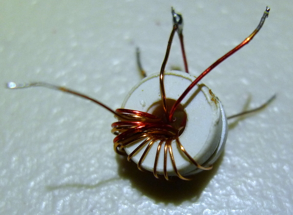
Two of the windings (there are three) each measure 22.1uH, in series they measure 88uH (as predicted by tight coupling).  I wouldn't necessarily recommend this particular coil form for Theremin work as it could easily be very temperature sensitive (ferrite formulations usually heavily favor small size over temperature dependence).  An IF transformer might be a better choice because it is normally used in resonant mode, and thus designed for that.  But a ferrite torroid might be an OK place to start, and if temperature dependence is a problem, then pick something else.

If you want a good LC meter for this kind of work, I recommend the inexpensive resonant type you can buy on eBay:

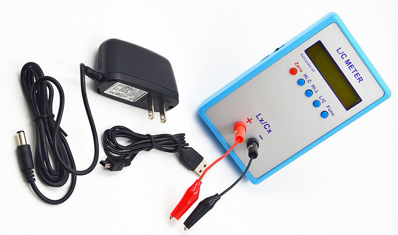
It's sensitive enough to (sort of) measure antenna intrinsic capacitance (~10pF) directly, which is kind of amazing.

I also wanted to mention something I stumbled across a while back [LINK] which I've dubbed "the invariant".  All simple analog heterodyning Theremins have essentially the same response in terms of octaves per given hand movement.  If you don't have the right inductor, within limits you can use any value inductor and then adjust the value of the padding capacitor across the antenna, and you will get the same heterodyned response as output.  You don't tune for absolute frequency, but for heterodyned response.  So: if you can get the thing to oscillate reliably, then you can likely adjust things to be indistinguishable from the original circuit.

Are you guys not using spice?  LTSpice is free and works well for Theremin oscillator explorations.

Posted: 5/11/2020 8:45:55 PM
apetechnology

Joined: 5/5/2020

I ordered some samples of the SWB-3040 and they are enroute. Free is always the best price! I will experiment with those. If that won't cut it we will try some of the IF transformers, or wind our own.

I am not as proficient in Spice as I just picked it up a few months ago - this project is still kind of a hands on, pen and paper kind of job. We adopted some of the old techniques of board layout generation as well to restore a system housed at University of Michigan. I did plug your sketch into Spice it and was able to make some measurements and play with the values enough for further experimentation.

Dewster, you've been an invaluable source of info here, I feel like this is a field of electronics where I need to admit I know less than I pretend to. We will be documenting the module on our website, I'll be sure to give you credit when we get this thing up and running.

Posted: 5/12/2020 2:03:34 AM
dewster

From: Northern NJ, USA

Joined: 2/17/2012

"I am not as proficient in Spice as I just picked it up a few months ago - this project is still kind of a hands on, pen and paper kind of job. We adopted some of the old techniques of board layout generation as well to restore a system housed at University of Michigan. I did plug your sketch into Spice it and was able to make some measurements and play with the values enough for further experimentation."  - apetechnology

I hope that didn't come across as harsh, I didn't mean it that way.  But some simple Spicing might help you determine if a circuit will even work, or narrow down component values or notations (is that a connection or a crossing?) when things look cryptic, weird, etc.  Spice has really helped expand my understanding of what's going on with Theremin oscillators; reconciling reality with simulation can be quite educational.  I can't imagine doing anything non-trivial in the way of analog or digital design and not simulating it in some way (though I realize you're probably not exactly doing design work here).

"...I feel like this is a field of electronics where I need to admit I know less than I pretend to."

Theremins are an amazing way to get an intuitive grasp of capacitance and inductance.  I knew very little about inductance before my research - inductors these days are the poor step children in the passives family.

Good luck!

You must be logged in to post a reply. Please log in or register for a new account.