Armstrong, Hartley, Colpitts, Clapp, Wallin...

Posted: 12/31/2020 6:12:23 PM
Buggins

From: Porto, Portugal

Joined: 3/16/2017

RC PLL doesn't look good enough.

Trying to design custom one.

VCO will have the same schematics as main oscillator. LC should give stable noise free performance.
Stuck trying to turn current sense oscillator into voltage controlled one.
BBY65-02 varistor parameters look fine, but I cannot figure out how to change frequency using it.
Probably, high LC swing may be a problem.

Posted: 12/31/2020 7:08:35 PM
dewster

From: Northern NJ, USA

Joined: 2/17/2012

"It's suitable only for drive signal range 0.7..VCC-0.7V. W/o load it's output looks like rail-to-rail, but under load it's getting limited by 0.7V offset."  - Buggins

High voltage is fun, but honestly, once you've got ~100Vpp at the antenna, any more is probably diminishing returns.  Way off resonance, the buffer provides the proper duty cycle to return to the lock state over a very wide range and through multiple sub harmonics, which is not usually the case for an XOR PLL, and is way more valuable than super high antenna voltage IMO.  You do want to use the XOR phase detector because it is relatively immune to edge noise.

"Phase is locked near 0, using phase comparator 2."

Don't you want a 90 degree lock for the XOR phase detector?  C divider will give you that.

Posted: 9/15/2021 7:01:40 PM
Buggins

From: Porto, Portugal

Joined: 3/16/2017

Trying to bypass touch issue of my LT1711 comparator based current sensing oscillator.

LTSpice model (download link):

I hope, playing with R1..R3, C1, C2 may help to avoid issues with touching uninsulated antenna.

LTC6752 has higher performance than LT1711.

According to simulation, phase shift between inductor current and drive signal is 5-7ns (about 0.5% of oscillator signal period).

Depending on inductor parameters, antenna voltage swing may be 250..600Vpp when powered from 3.3V

Going to design PCB and try to solder and test it on real hardware.


Posted: 9/27/2021 4:23:12 PM
Buggins

From: Porto, Portugal

Joined: 3/16/2017

Trying to build current sensing oscillator with PLL.

For current sensing approach, inductor current is in-phase with drive signal.
It's hard to detect lock PLL on zero phase shift, but pretty easy to do it on PI/2 phase using XOR phase detector. Exact PI/2 phase shift and precise 50% duty cycle are required.
Possible solution could be VCO with quadrant (two PI/2 shifted) outputs.
Triangle oscillator (schmitt trigger + integrator) gives pretty good triangle for driving LC tank, and PI/2 shifted square for using as XOR input.
Unfortunately I cannot figure out how to control its frequency.

I've built VCO similar to 555 schematic (see article), with frequency controlled by threshold voltage. lvc1g74 is used as RS trigger, changing its state on triangle level threshold comparator signals. 

Inductor current is sensed with resistor and comparator.
XORing of sensing comparator output and PI/2 shifted squared drive signal gives 50% duty cycle at resonance.
XOR output is integrated on opamp and gives control voltage for VCO.


Download link

Needs some component models available here


Simulation results:

D FF output, triangle drive signal, R_Sense/inductor current


VCO control voltage and inductor current: PLL locks on resonance


Voltage swing on antenna


This implementation is a bit expensive.

Going to try finding simpler solution.

Higher frequency (with hand far from antenna) has lower triangle voltage swing - more affected by noise than high swing lower frequencies.
Voltage controlled current source could help to replace triangle swing frequency control with fixed (max) triangle swing current control.


Posted: 10/3/2021 6:45:35 PM
Buggins

From: Porto, Portugal

Joined: 3/16/2017

Learned interesting thing about using of opamps.

There are a lot of cheap enough opamps with 50-250MHz bandwidth.
But trying to make current sensing oscillator on these opamps gives very big phase shift (up to PI/8) between R_sense current and drive signal from opamp.
When I'm passing sine to follower or amplifier on the same opamp, I see very small phase shift between input and output (2.4ns for 3.3Vpp 1MHz for ad8651) - pretty good for current sensing oscillator. What is a reason? It looks like opamp performance degradation is caused by saturation. If we can find some solution for limiting of opamp output within working range to avoid saturation, we could implement nice oscillator using opamp.

Posted: 10/3/2021 7:54:27 PM
dewster

From: Northern NJ, USA

Joined: 2/17/2012

Vadim, I'm looking at the AD8651 datasheet:

https://www.analog.com/media/en/technical-documentation/data-sheets/AD8651_8652.pdf

One thing that sticks out is the output impedance vs. frequency, Figure 33 on page 10.  This part seems unusable just because of that.  Many tens of ohms even below 100kHz, with no spec above that.  Perhaps it isn't tracking because of that, then the 100ns or so recovery time kicks in?  I dunno.  Maybe try buffering the output with transistors and including them in the feedback loop?  Might as well roll your own then with discretes.

I think opamps are yet another part in a long list of parts that are poorly suited for Theremin oscillator work.  You don't want an idealized amplifier (infinite gain, infinite input impedance, etc.).  What you want is something that has rather horrible specs for general use, and they tend not to make them because they would look pretty awful on paper.  The spec sheet would be filled with caveats for folks thinking it's an opamp.  Same for coils, no one would buy a Theremin coil except a Theremin designer, and we're pretty rare with very low demand.  Everyone else wants the tiniest choke possible, damn the SRF.

Posted: 10/4/2021 5:11:50 PM
Buggins

From: Porto, Portugal

Joined: 3/16/2017

So, it looks like opamp with fast overdrive recovery is needed. I've found a few, but all of them are 5V or higher supply voltage.
Tried to implement some limiter on opamp, but failed to achieve small delay.

Posted: 10/11/2021 8:35:25 PM
Buggins

From: Porto, Portugal

Joined: 3/16/2017

Yet another current sensing oscillator on BJTs.


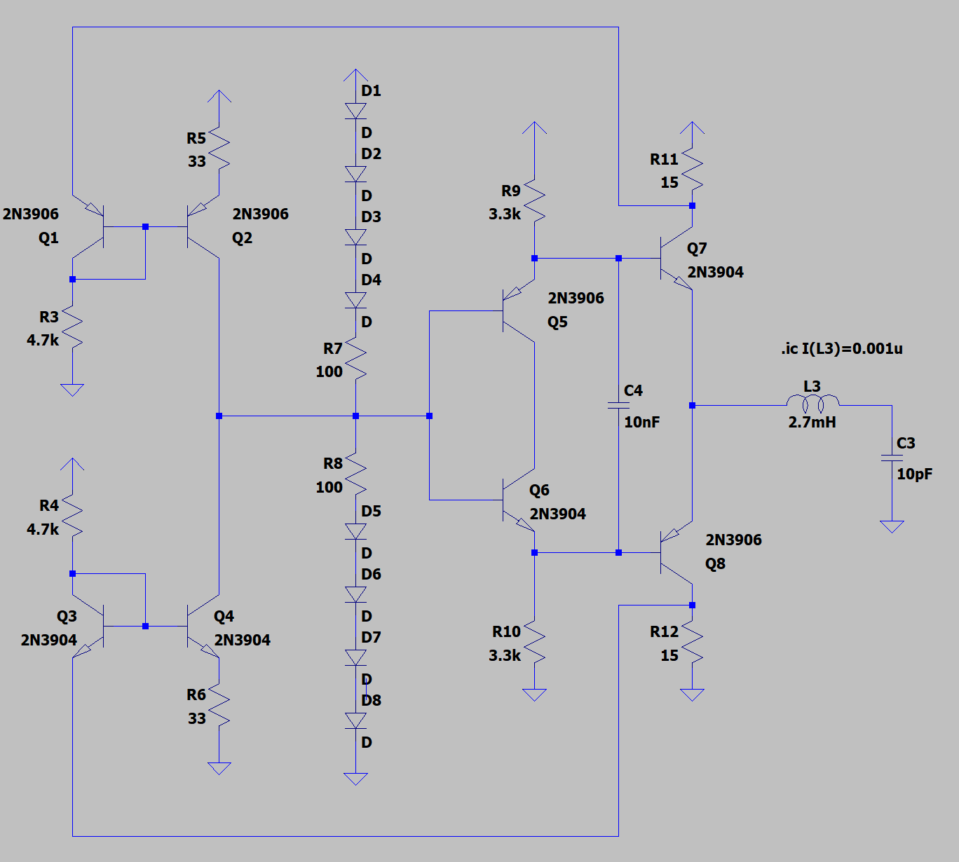
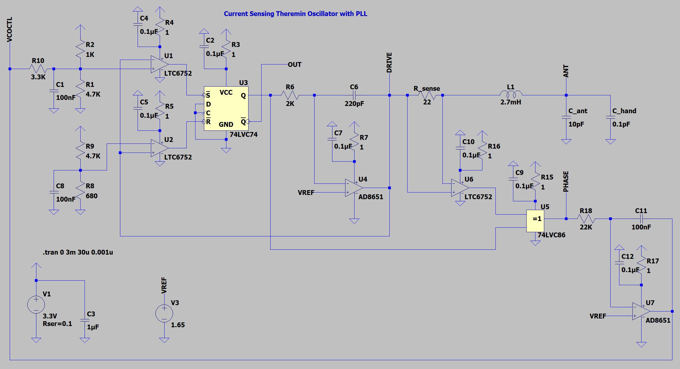
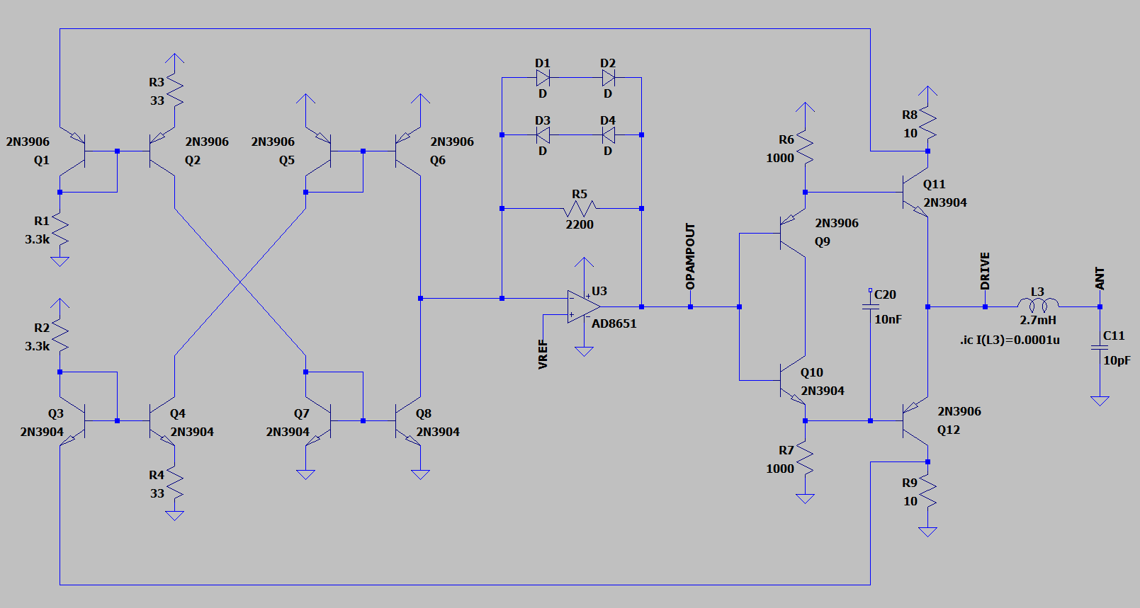
Drive cascade mostly borrowed from dewster's diff amp oscillator.

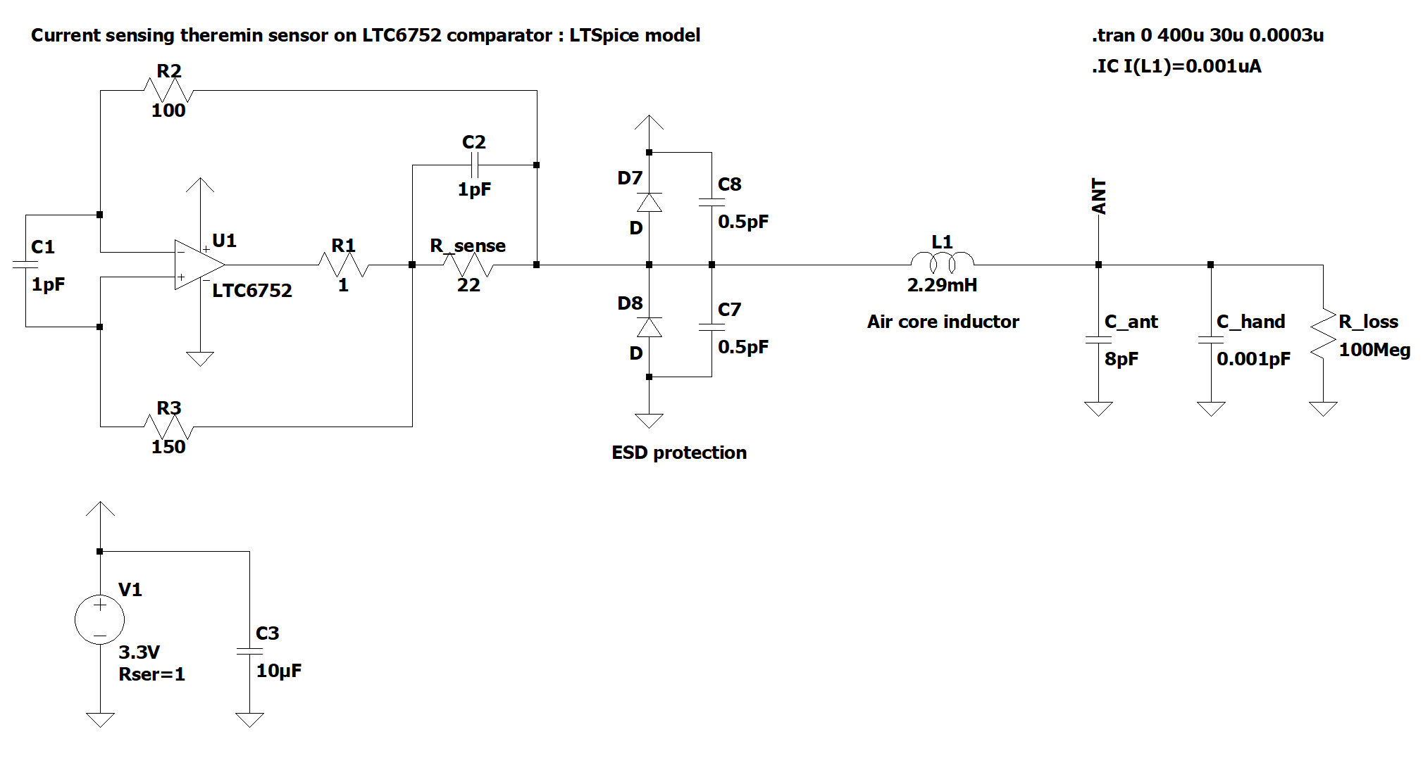
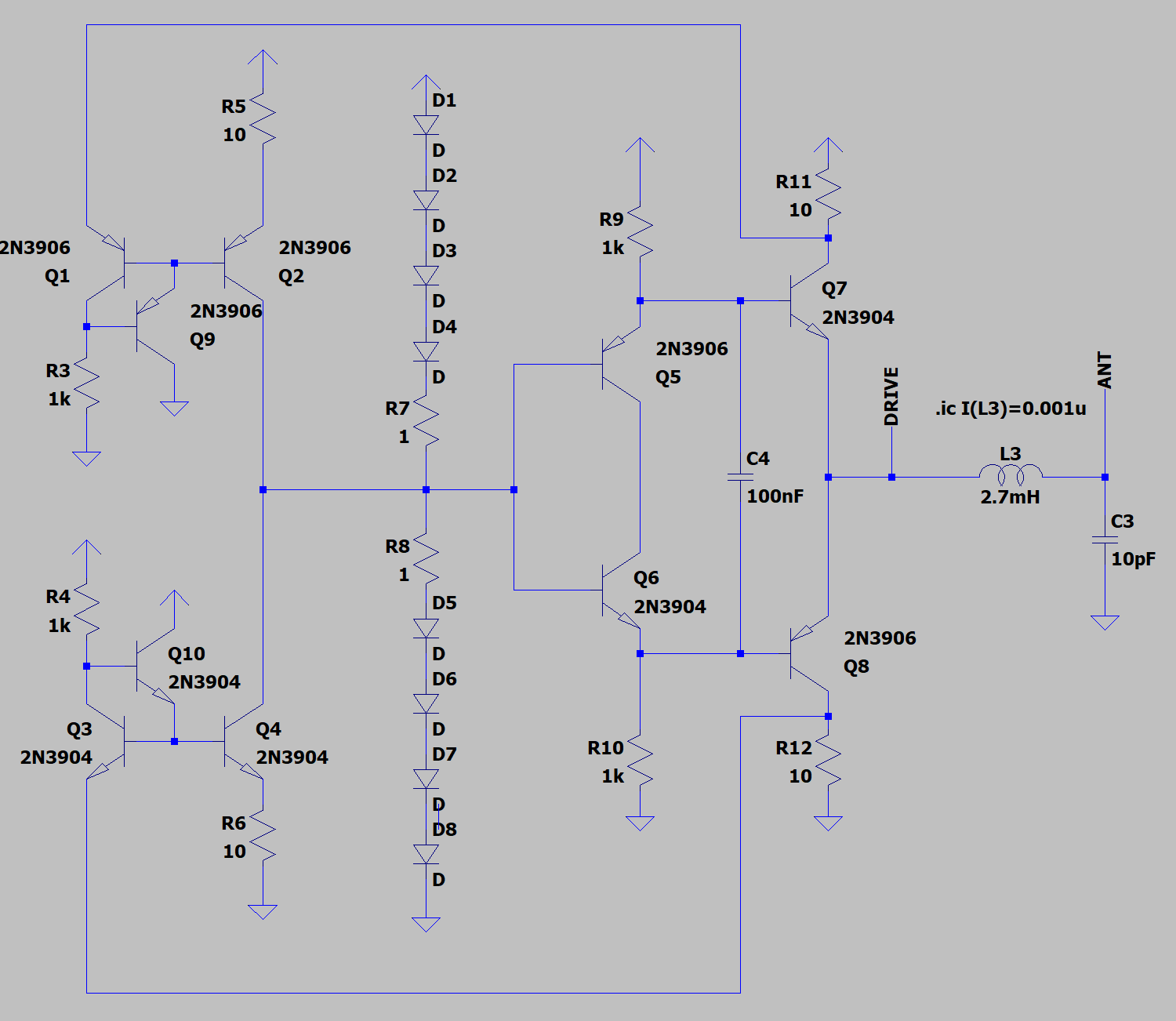
The difference is a location of R_sense. Sensing resistors are placed between output cascade and power rails.

Instead of differential amplifier, current sensing is implemented using current mirrors. One mirror senses from 3.3V rail, second one - from 0V rail.
Current sensing from rails is pretty simple, comparing to BJT differential amplifier.

Mirror outputs are being combined, to obtain difference between top and bottom rail currents. It's equal to LC tank current.

Main challenge is to keep phase error (amplifier delay) as small as possible.

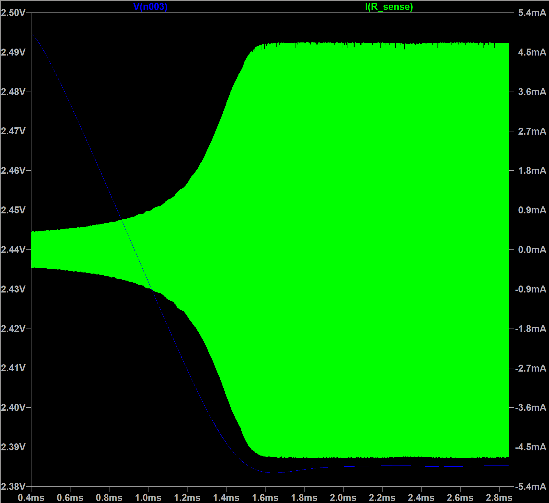
While offered current is fully consumed from current mirror output, delay is small enough.
But if output current is not consumed, delay appears.

I've added diode based limiter, to source/sink mirror output current when sense output voltage is close to power rail.


spice model: download link


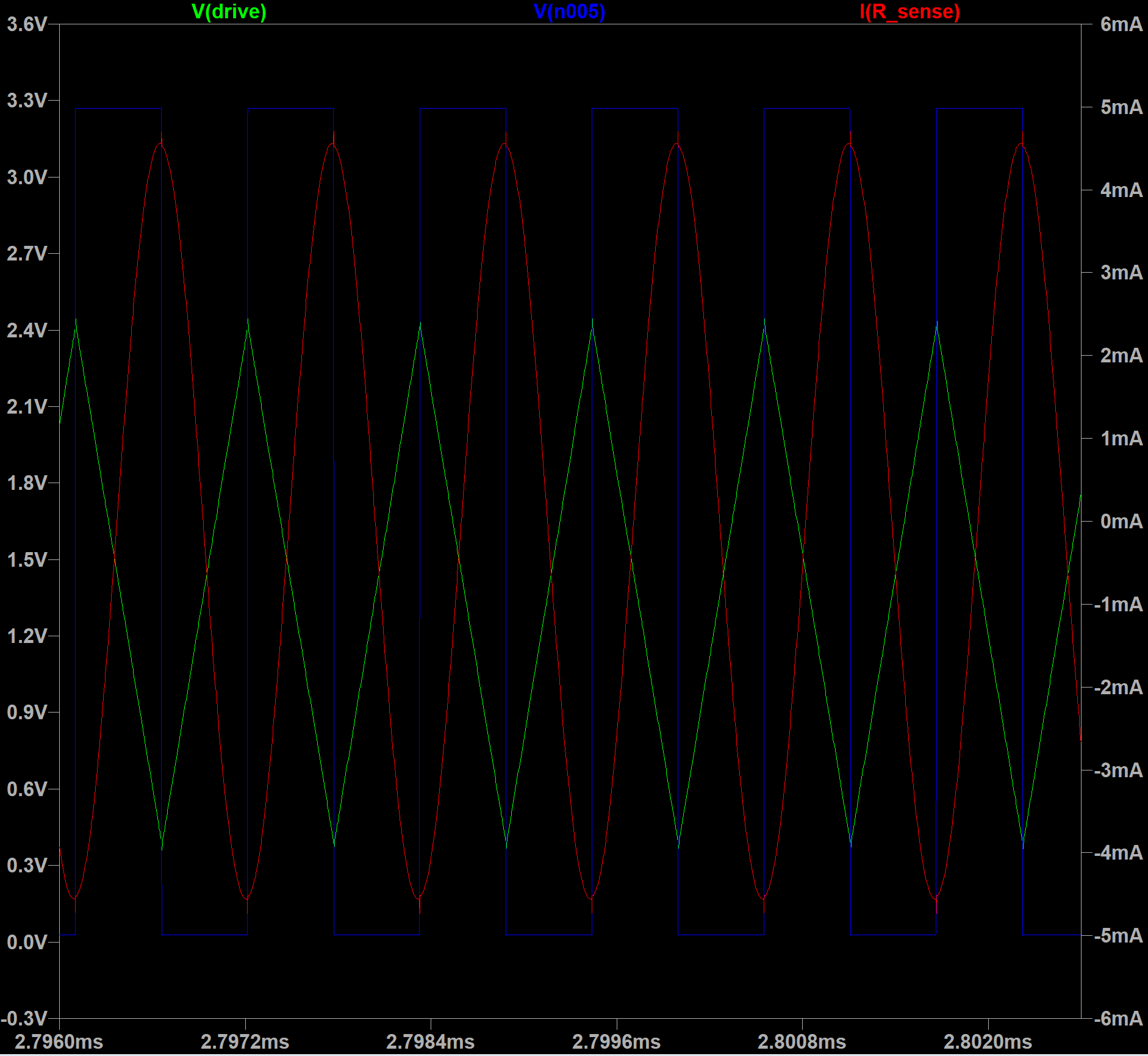
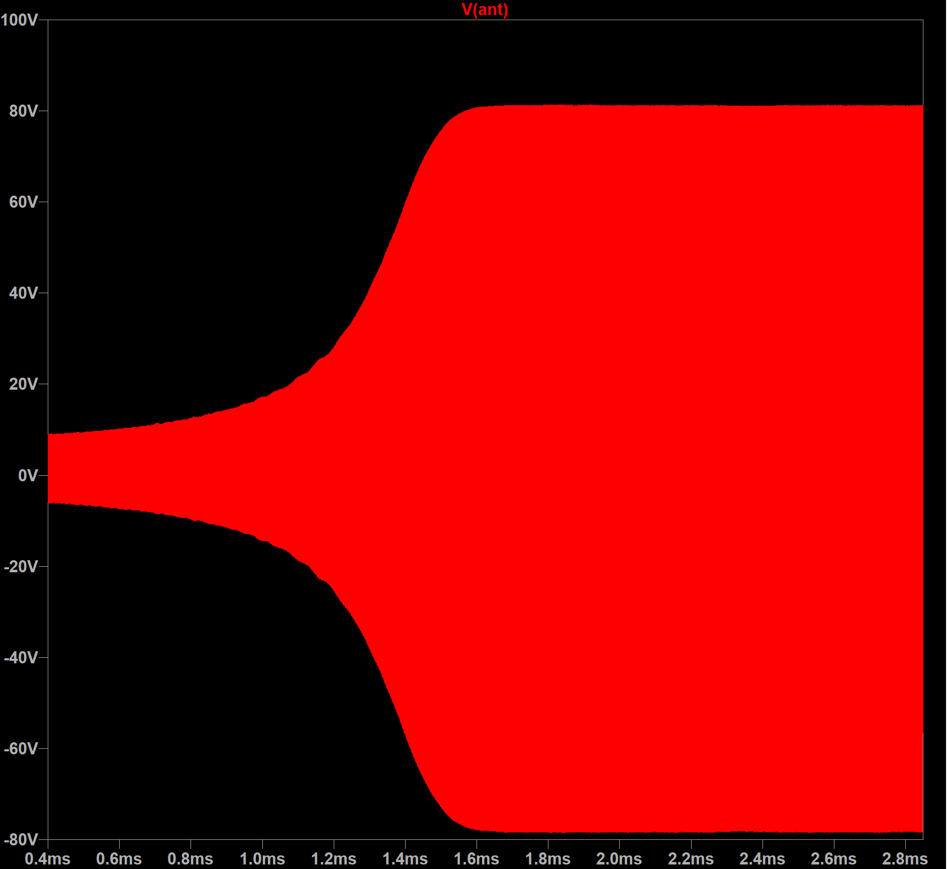
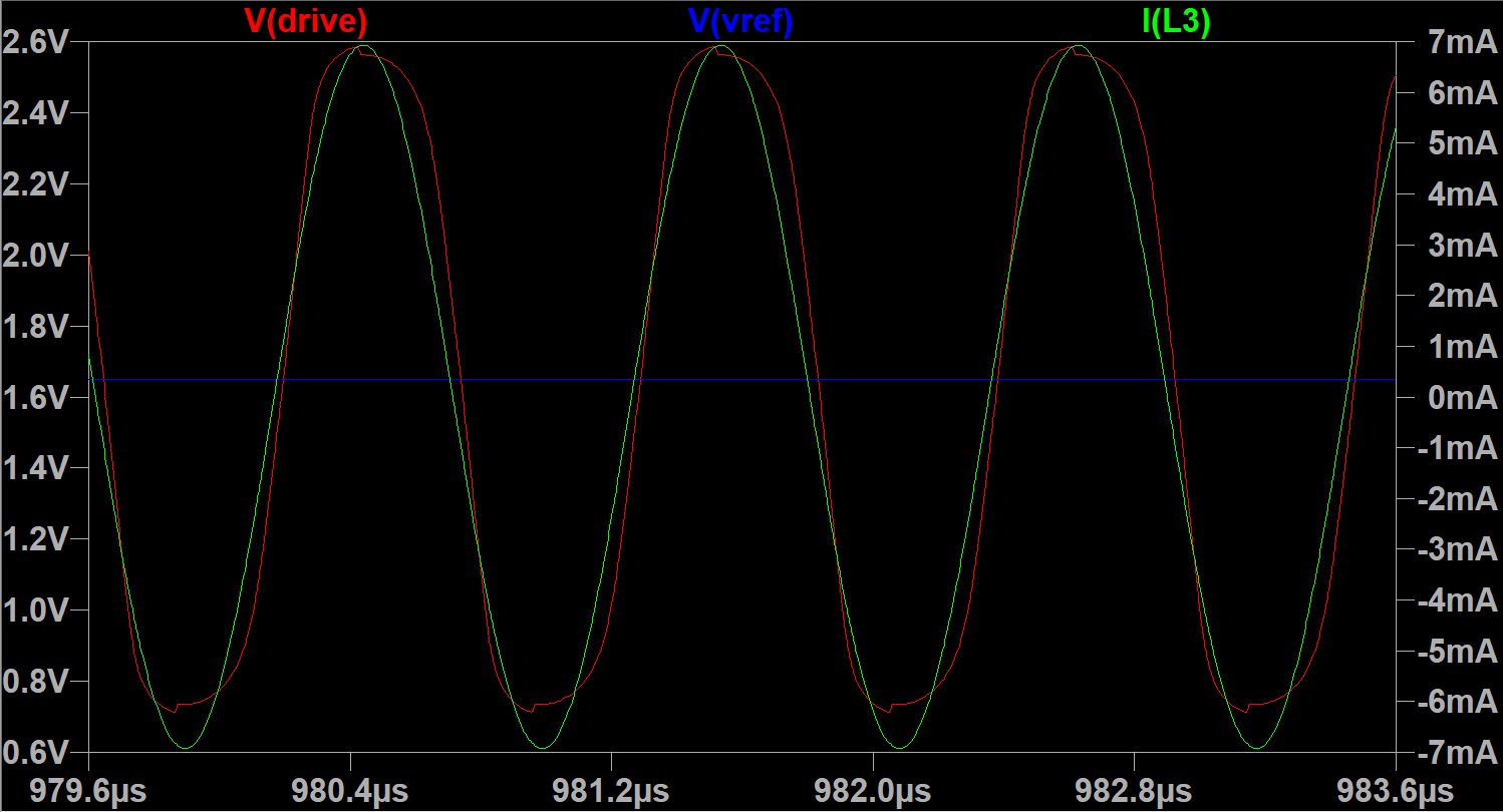
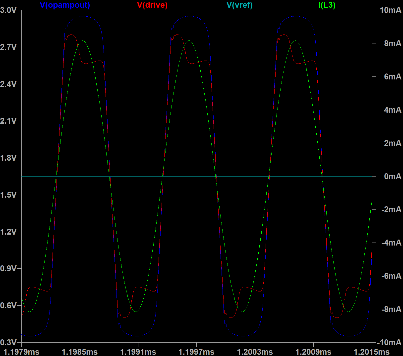
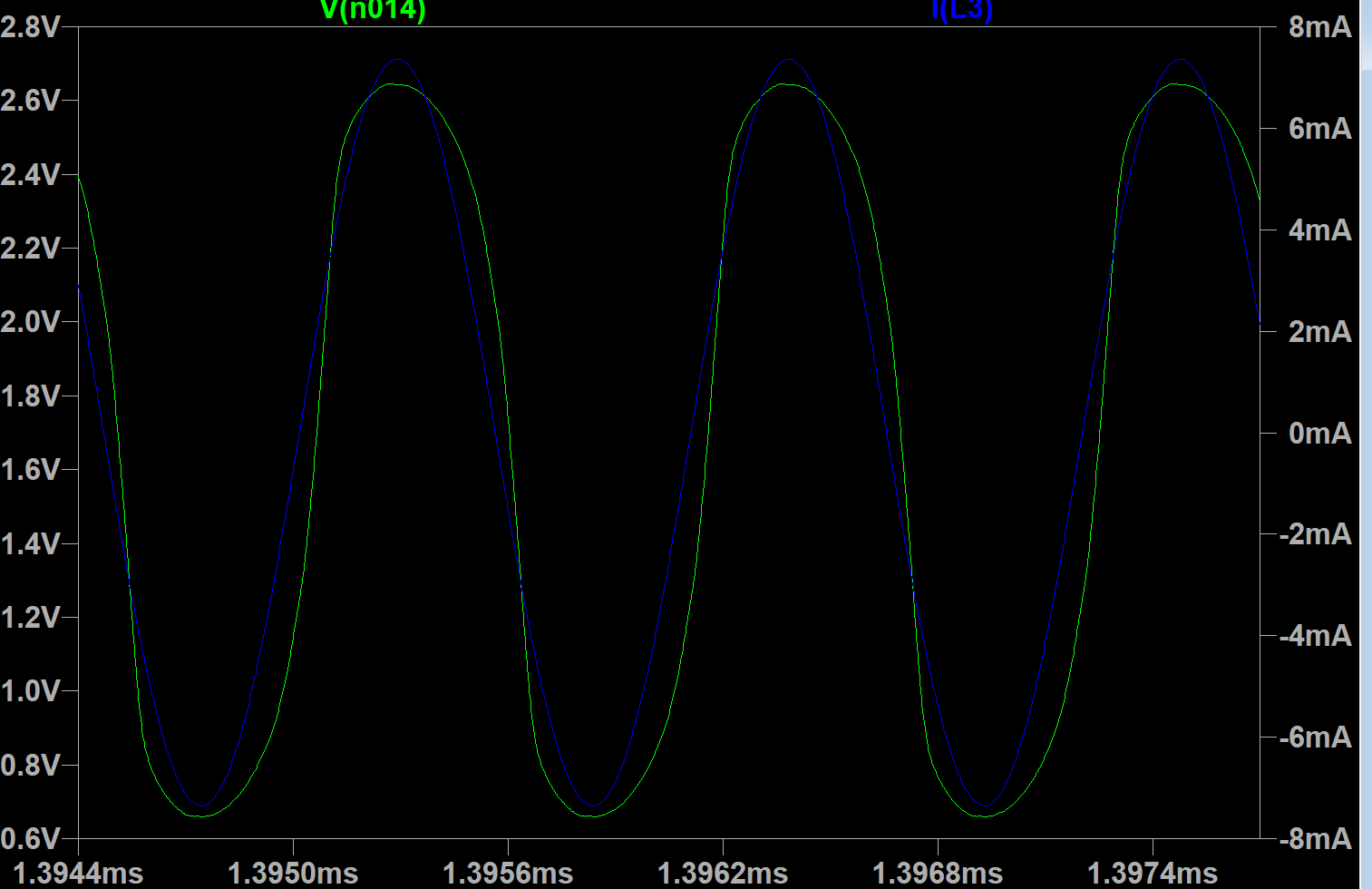
Drive signal and LC tank current:

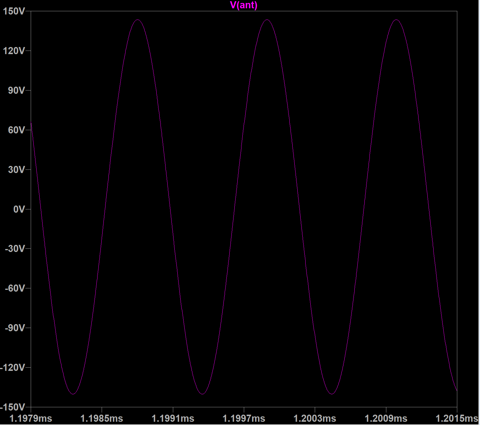
Voltage swing depends on inductor and LC tank Q.

With 2.7mH R_ser=120 Ohm, C_par=1.5pF -- antenna voltage swing is 250 Vpp
With 2.7mH R_ser=60 Ohm, C_par=1.5pF -- antenna voltage swing is 700 Vpp
With 2.7mH R_ser=30 Ohm, C_par=1.5pF -- antenna voltage swing is 1200 Vpp

Results are still far from perfect. Will try to tune for smaller inductor current do drive delay.

Posted: 10/12/2021 2:57:02 PM
Buggins

From: Porto, Portugal

Joined: 3/16/2017

Slightly optimized current sensing oscillator: 25ns delay between LC tank current and drive signal.

Drive signal swing is only 0.7..2.6V (3.3-2*0.7 = 1.9), antenna swing is 240Vpp for 120 Ohm 2.7mH inductor.


spice model: download link

As I see from simulation, current in current sensor mirrors has almost no delay from LC tank current.

Delay is introduced in mixer/limiter/current to voltage stage.

Redesign of this stage may improve oscillator performance (reduce phase error in drive signal).


As well, I'm trying to use two current mirrors - to provide drive signal close to supply voltage.
I think it's a nice idea to implement oscillator with two pairs of current mirrors.
Although, I have some troubles when trying to get it oscillating...


Posted: 10/13/2021 1:47:30 PM
Buggins

From: Porto, Portugal

Joined: 3/16/2017

Yet another current sensing oscillator.

It's fast enough (10ns phase delay). Dewster's BJT diff amplifier gives about 15ns delay.
Is able to provide high current - for low resistance inductors.
Drive signal amplitude is limited by output cascade 0.7V..VCC-0.7V


Drive amplifier output stage has resistors on its power inputs - we will use them for current sensing.
Difference between currents through top and bottom resistors is actully LC tank current.

Current sensing is implemented using two current mirrors.
Second pair of mirrors is just for inverting of current direction.

Opamp forms current to voltage converter with limit using diodes.

Simulation with 2.7mH inductor with R_serial = 120 Ohm

Output of opamp, drive signal and inductor current:


Voltage swing on antenna:

Spice model: download link

You must be logged in to post a reply. Please log in or register for a new account.