A digital theremin built with off-the-shelf components

Posted: 12/18/2020 7:06:38 PM
dewster

From: Northern NJ, USA

Joined: 2/17/2012

"I have never quite understood what the units are for the loop gain."  - Channel Road Amps

This is something I really puzzled over too when first getting into PLL design.  The units are phase, with the loop correcting phase error with negative feedback.  Probably the most confusing operator in the loop is the oscillator, which takes frequency as an input and kicks out phase.  Phase is the time integral of frequency, so the oscillator acts like an integrator.

"Suppose the loop gain is -2, and I measure a phase error of +10 degrees.  Does that mean I would apply a frequency correction that would change the phase error by -20 degrees, to -10?  (If so, it would be unstable, of course.)  Or am I misunderstanding the concept?"

The loop gain has to be negative and less than one, otherwise it will be unstable.  Using your example: if the loop gain is -0.5 then the +10 phase error is reduced to 10 + (-0.5 * 10) = 5.  On the next evaluation of the loop the error will be 5 + (-0.5 * 5) = 2.5, on the next it will be 1.25, etc. until at infinite time it is zero.  If you plot this it looks like a stepped first order low pass filter RC type response.  The -3dB point is directly dependent on the loop gain and how often you update the loop calculations: lowering the loop gain will lower the cutoff frequency and increase stability, updating the loop more often will increase the cutoff frequency.

Also, phase locking to a resonating LC is somewhat different than phase locking to an external frequency input.  The main difference is that there can never be a frequency difference, only a phase difference, between the I/O.  What this boils down to is you don't need - or even want! - a full-blown PID controller.  The P (proportional to error) feedback will introduce sticky spots in your field.  Normally two integrators in a row are unstable (explicit phase error integration and the oscillator) but in this case it is stable and exactly all you need.  So we find the phase error with an XOR gate, use this to count up and down (integrate) depending on the XOR output, right shift it to attenuate it (set the bandwidth and stability), and feed this to the oscillator (NCO).  Easy peasy in concept.

"Thanks for explaining the trick for measuring the voltage swing.  I assume you use a thin wire so that it doesn't act so much as an extension of the antenna."

This is something I'm currently struggling with.  For high voltage fields I think it's necessary to string several capacitors in series, with as long leads as possible to put distance between them.  Maybe 5x 4.7pF in series, or even 10x 10pF to be extra sure, leading to the final 100pF or 1000pF going to ground.  Mount it in a small diameter tube to make a DIY high voltage AC probe.  Maybe exponentially space the caps?

"Is it possible to make a 1 pF leaded capacitor that is really 1 pF in practice?"

For low voltages, I believe so.  For higher voltages it doesn't really work because the external field overwhelms the bulk C.  Same for large resistors.

"The pitch field can be stretched or shrunk by the leftmost knob.  I am trying to follow Carolina Eyck's theremin method, so the default makes one octave correspond to the change from her low note position (closed hand, tipped back) to her high note position (open hand).  (This has required me to unlearn my original playing technique, unfortunately.)  By turning the knob, you can stretch or shrink the pitch field in increments of ¼ inch per octave, while keeping it linear."

Ohh, fascinating!  I can't imagine an argument for higher sensitivity (shrunken pitch field) then the rather high (IMO) invariant sensitivity of the analog Theremin on which all playing methods have been necessarily based, but I wonder if there is a (TBD) method most would find more ideal with lower sensitivity?

Posted: 12/18/2020 8:29:11 PM
Channel Road Amps

From: Lopez Island, WA

Joined: 11/25/2014

Buggins,

What are the benefits from PLL?

It improves noise immunity by keeping the amplitude of the measured signal as large as possible.  It accomplishes that by ensuring that the RLC antenna circuit is always driven at its resonant frequency, which of course changes with the motions of the player's hand.

Originally, I did not implement a PLL.  The digital oscillator was simply set to the RLC resonant frequency in the hands-withdrawn position, and it was not changed after that.  The software measured the phase difference between the excitation and the sensed voltage and used it directly to control the pitch or volume.  It actually worked pretty well.  But when the phase difference deviated very far from 90 degrees (i.e., when the antenna circuit was far from resonance due to increased hand capacitance), the signal became very small.  I implemented the PLL because I thought it would probably work better when the signal was large at all times.


Any oscillator is internally PLL which tracks constant phase for excitation signal.
Probably, measure of phase shift is just easy measurable by low resolution timer (difference between excitation signal frequency and LC resonant frequency is zoomed in with LC Q as phase shift).
Frequency of excitation signal is being updated slowly by soft PLL while oscillator reacts on C change instantly.


I'm not sure I understand what you're saying.  But since you mention the oscillator reacting to a change in capacitance, I assume you are talking about an analog RLC oscillator.  A primary goal I had was to avoid using analog oscillators.  I wanted to eliminate the problems of drift and tuning that are inherent in analog oscillators.  Digital oscillators use a crystal time base that is almost perfectly stable.


John, do you see 60Hz main hum noise in sensor data? What is a hand to antenna distance for which main hum becomes visible?


I haven't checked explicitly for 60 Hz noise, but I don't hear any 60 Hz hum in the audio.  When I'm standing in the playing position with my hand drawn back to the edge of the pitch field, I do hear a little bit of wobble in the tone.  That occurs around 18-20 inches from the antenna.  But I think it might be caused by the way my software tries to get a linear pitch field.  Beyond 18 inches the software intentionally ramps the frequency of the pitch down to zero fairly quickly, so that the tone stops entirely when the player steps away from the instrument.

John

Posted: 12/18/2020 10:23:15 PM
Channel Road Amps

From: Lopez Island, WA

Joined: 11/25/2014

Dewster,

I really appreciate the education you're giving me on PLL theory.  Your explanation makes perfect sense to me.  The code I implemented is a little bit different in detail.  I will describe it, and maybe you can help me understand what the actual loop gain is.  In each PLL, this loop executes PLL_SAMPLERATE (currently 1000) times per second.

- Measure the phase.
- Calculate the phase error, which is just the difference between the phase and pi/2.  (Everything is done in terms of radians and radians per second.)
- Set or clear an is_locked flag according to whether the phase error is less than 10 degrees or not.  In practice, it is always locked except when the player touches the antenna.
- Do the math to convert the phase error to a frequency error w_error, again in radians per second.  The math just answers the question, "If I am driving the RLC circuit at and the phase is , what is the resonant frequency of the RLC circuit?".  Then w_error is the difference between that and the oscillator frequency.
- Update the oscillator frequency w like this: w += K * w_error.

I think that in PID controller terminology, this amounts to strictly integral control: no P and no D.

The constant K is currently 500.0 / PLL_SAMPLERATE, i.e., 0.5.  It is expressed in terms of PLL_SAMPLERATE so that the time constant remains the same no matter what the sample rate is.

Anyway, I'm not sure how to express this in terms of loop gain.

John

Posted: 12/19/2020 3:34:58 PM
dewster

From: Northern NJ, USA

Joined: 2/17/2012

"I really appreciate the education you're giving me on PLL theory." - Channel Road Amps

I very much appreciate you sharing the fascinating details of your implementation!  I think we all benefit considerably from the documentation of open development projects such as yours.  In engineering, nothing succeeds like success.

"- Measure the phase.
- Calculate the phase error, which is just the difference between the phase and pi/2.  (Everything is done in terms of radians and radians per second.)
- Set or clear an is_locked flag according to whether the phase error is less than 10 degrees or not.  In practice, it is always locked except when the player touches the antenna.
- Do the math to convert the phase error to a frequency error w_error, again in radians per second.  The math just answers the question, "If I am driving the RLC circuit at and the phase is , what is the resonant frequency of the RLC circuit?".  Then w_error is the difference between that and the oscillator frequency.
- Update the oscillator frequency w like this: w += K * w_error.
I think that in PID controller terminology, this amounts to strictly integral control: no P and no D."

I agree that what you are describing is integral only control, which is what you want in an LC DPLL.

"The constant K is currently 500.0 / PLL_SAMPLERATE, i.e., 0.5.  It is expressed in terms of PLL_SAMPLERATE so that the time constant remains the same no matter what the sample rate is.
Anyway, I'm not sure how to express this in terms of loop gain."

You are calculating and normalizing the LC Q phase gain, and it seems you are also normalizing the phase detector gain, which simplifies the loop gain calculations down to K.

First order low pass digital IIR filters are really mushy and they completely poop out at Nyquist (1/2 the sample rate, which in your case is 500Hz).

The exact cutoff (-3dB) point of a digital first order IIR low pass filter for a given attenuation factor K is:

  Wc = ACOS( ( K^2 + 2K - 2 ) / ( 2K - 2 ) )

where Wc = 2 * pi * Fc / Fs, so:

  Fc = Wc * Fs / 2pi

For K=0.5 and Fs=1kHz:

  Wc = ACOS( ( 0.5^2 + 0.5*2 - 2 ) / (2 * 0.5 - 2 ) = ACOS((0.25 + 1 - 2) / (1 - 2)) = ACOS(-0.75/-1) = ACOS(0.75) = 0.722

  Fc = 0.722 * 1000 / 2pi = 115Hz

And for small K this can be approximated by:

  Fc ~= K * Fs / 2pi

because the ACOS term goes to 1.

Regarding series R:
1. You mention an 'R' component in the RLC phase calcualation - is this the DCR of the coil, or is there some added bulk resistance?
2. You describe how you were initially using a fixed LC stimulus frequency and calculating hand position from phase difference.  As you must be aware, one way to keep the antenna voltage more constant in that scenario is to somewhat kill the Q with added LC series resistance, though that lowers the antenna voltage overall.  Did you experiment with added R to expand the phase change range (lower the Q phase gain)?  Did you find the non-linearity of the phase response to be a particular bane (or boon)?

Posted: 12/20/2020 12:31:18 AM
Channel Road Amps

From: Lopez Island, WA

Joined: 11/25/2014

Dewster, again that's a great explanation.  One consequence, which I should have realized but didn't: my cutoff frequency isn't truly independent of the sample rate, due to what happens when the cutoff frequency gets too close to the Nyquist frequency.


Regarding series R:

1. You mention an 'R' component in the RLC phase calcualation - is this the DCR of the coil, or is there some added bulk resistance?


I meant for the R to stand for the DC resistance plus all other losses in the antenna circuit.


2. You describe how you were initially using a fixed LC stimulus frequency and calculating hand position from phase difference.  As you must be aware, one way to keep the antenna voltage more constant in that scenario is to somewhat kill the Q with added LC series resistance, though that lowers the antenna voltage overall.  Did you experiment with added R to expand the phase change range (lower the Q phase gain)?  Did you find the non-linearity of the phase response to be a particular bane (or boon)?

I was aware that a lower Q would keep the antenna voltage more constant, but it never occurred to me to lower the Q intentionally by adding series resistance.  That's an interesting idea!


As for whether I found the non-linearity of the phase response to be helpful or harmful, I really didn't pursue it far enough to form an opinion about that.  Almost immediately, I started working on the PLL implementation--mostly because I wanted to learn more about that.  Also, at that point I wasn't yet even trying to calculate the hand position or to achieve pitch field linearity.  The whole circuit was sprawled out on my crowded workbench with different antennas and way too much metal in the vicinity.

Posted: 12/20/2020 4:29:56 PM
dewster

From: Northern NJ, USA

Joined: 2/17/2012

"One consequence, which I should have realized but didn't: my cutoff frequency isn't truly independent of the sample rate, due to what happens when the cutoff frequency gets too close to the Nyquist frequency."  - Channel Road Amps

Good point.  A higher sample rate would make the cutoff more constant, though if your LC has a high Q and operates at all off of resonance (say during rapid hand movements, or particularly with an antenna touch) the cutoff probably varies more that way than any other, but you are actively compensating for this in software and I'm not, which makes me wonder if I should be setting the D-Lev cutoff higher.  If nothing seems amiss then no need to change anything, though it never hurts to better understand what's going on.

With all that horsepower, have you considered adding an active pitch display?  It makes it much easier to play sans accompaniment, and it can reveal the key and melody structure too.  A pitch display enables chromatic pitch correction, and both of these definitely improve my playing.  For as unmoored as the Theremin is in the pitch department, and for how painful that can be to listen to (even for the performer), I consider them to be essential features.

Posted: 12/20/2020 11:57:45 PM
Channel Road Amps

From: Lopez Island, WA

Joined: 11/25/2014


Dewster,


With all that horsepower, have you considered adding an active pitch display?  It makes it much easier to play sans accompaniment, and it can reveal the key and melody structure too.  A pitch display enables chromatic pitch correction, and both of these definitely improve my playing.  For as unmoored as the Theremin is in the pitch department, and for how painful that can be to listen to (even for the performer), I consider them to be essential features.

I agree that would be a nice feature.  I would definitely use it to come in on-pitch for the first note. After the first note I trust my ears, thanks to years of singing in choirs and playing the pedal steel guitar (not at the same time!).  OK, everybody stop laughing please.  I know there was some painfully bad intonation in the recording I made, but that's because I'm a poor theremin player, not because I don't know when I'm flat or sharp. 

Posted: 1/20/2021 9:19:52 PM
Channel Road Amps

From: Lopez Island, WA

Joined: 11/25/2014

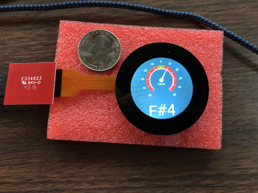
Dewster's suggestion of adding a pitch display was keeping me awake at night, so I started looking into what's available.  I've been messing around with this nifty 1.3" round PixxiLCD intelligent display from 4D Systems:

It's a pretty cool little device.  It has a collection of built-in widgets (buttons, gauges, etc.) that you can configure with a drag & drop application on a PC.  Then controlling the widgets is done through a simple communication protocol over an async serial link.  The messages are short and at a high-level of abstraction, e.g., set a gauge to a given value, display a given string, etc.  The model I bought has a touch screen, which opens up some interesting possibilities.  (Though it's so small that it's hard to operate without a stylus.)

Now I just have to figure out how to mount the thing where it's clearly visible without interfering too much with the pitch field.

Posted: 1/21/2021 2:45:52 AM
dewster

From: Northern NJ, USA

Joined: 2/17/2012

"Now I just have to figure out how to mount the thing where it's clearly visible without interfering too much with the pitch field." - Channel Road Amps

Try updating the display at your axis sampling rate.  That might kill enough of the interference by placing a zero there (this is what I do with the D-Lev LED tuner - 48kHz).  The 20 x 4 character LCD is also a potential problem with the D-Lev, I got around it by updating it only when things were changing (spinning encoders).

Posted: 1/21/2021 11:47:43 PM
Channel Road Amps

From: Lopez Island, WA

Joined: 11/25/2014


Try updating the display at your axis sampling rate.  That might kill enough of the interference by placing a zero there (this is what I do with the D-Lev LED tuner - 48kHz).  The 20 x 4 character LCD is also a potential problem with the D-Lev, I got around it by updating it only when things were changing (spinning encoders).


Hmm, the problem I was thinking about was just having more grounded stuff in the pitch field.  I hadn't considered electrical interference from the display module, but that's a definite possibility.  I haven't installed the display in the actual theremin yet; I've just tried it stand-alone connected to a spare Nucleo board running some test code.  I think I'll need to install the display in the theremin and see what happens, and then deal with it at that point.

What did you mean by "axis sampling rate"?  I was planning on updating the display at the same rate at which the pitch is updated (100 Hz), or possibly at some fraction of that rate.

You must be logged in to post a reply. Please log in or register for a new account.