


Hola hello
I am trying to measure the antenna voltage with an oscilloscope, what is the correct way to do it?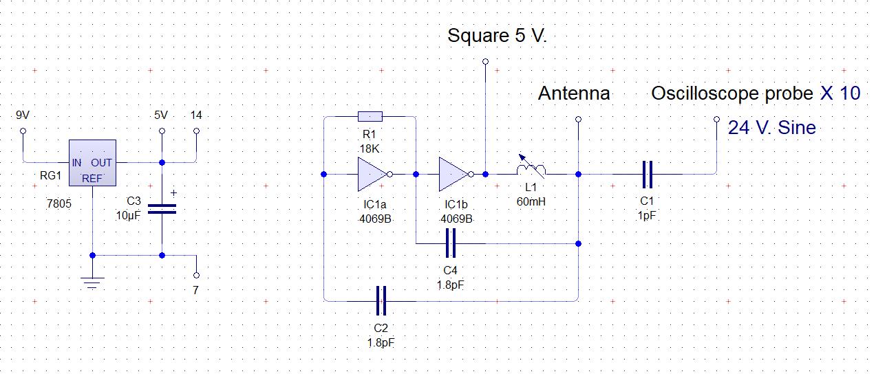
This is how I am trying to measure, is that correct?
Saludos.
"I am trying to measure the antenna voltage with an oscilloscope, what is the correct way to do it?" - Goño
A single 1pF won't load the probe enough, and stray pickup will probably give you a higher reading than is real.
The most accurate way that I've found is to make a high voltage probe from a series of resistors and capacitors in parallel, which also puts some distance between the probe and the HV source. The resistance and capacitance should be the nominal impedance of your 10x scope probe. I used 15pf in parallel with 10Meg, 9 of these in series, the probe forms the tenth RC, to produce a 100x probe. Keep the lead lengths short to minimize the inductance, it might actually be better to use surface mount here.
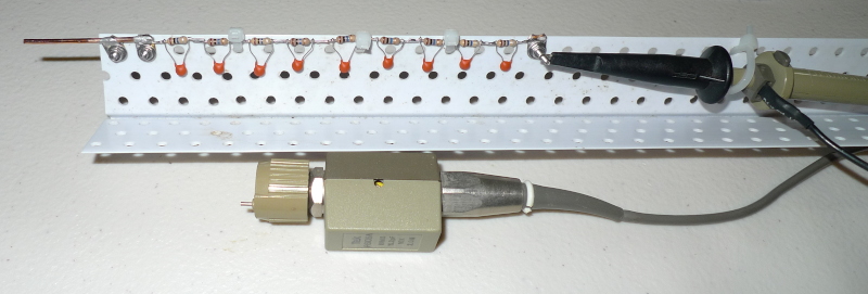
I also used an old scope probe so that I could calibrate it and leave it permanently attached - calibration of the probe is critical for getting accurate readings at higher frequencies.
It's all mounted on a section of plastic drywall corner that I had laying around. Small zip ties work well. It's not pretty but I don't care as long as it works.
Keep in mind that even this probe with 1.5pF || 100Meg and unknown inductance is a significant load for a Theremin, so you'll definitely be perturbing the operation of your oscillator with it. Theremins are one of those things in physics where observation directly influences the experiment.
Thank you very much Buggins and Dewster.
The probe measures 18pF, 10M in 10x, I don't have 18pF but I have 27pF and 56pF in series, it would give me around 18.2pF and 10M in parallel, this could be like Dewster says x9 and the probe in series to get 1.8pF, is that correct? I don't want extreme precision, just a little light on the numbers.
Sorry for my English.
Goño, I think you have it right, you would put an 18pF in parallel with a 10Meg resistor, make 9 of these, and then connect them together in series.
You say you measured the probe capacitance? Capacitance that low is difficult to measure with good precision.
Also, probes have a compensation capacitor inside that you can adjust with a plastic screwdriver. You might want to see what the capacitance of the probe is in the middle of the adjustment range, and use that value for the RC ladder. I had to search though my probe "junk box" to find one that had sufficient adjustment range for the 15pF || 10Meg ladder.
You say you measured the probe capacitance? Capacitance that low is difficult to measure with good precision.
Yes, I measured it with several multimeters, it was between 17pF to 19pF and yes, the numbers were not very accurate, but I also checked the characteristics of the model and it goes from 18.5pF to 22.5pF, the 2 that I have were at the same value, it should set it to 20pF?.
Also, probes have a compensation capacitor inside that you can adjust
Yes I know and according to I have them adjusted, I did it by squaring a square wave that comes out of the same oscilloscope that I have.
"Yes, I measured it with several multimeters, it was between 17pF to 19pF and yes, the numbers were not very accurate, but I also checked the characteristics of the model and it goes from 18.5pF to 22.5pF, the 2 that I have were at the same value, it should set it to 20pF?." - Goño
I guess I'd aim for that region. You're smart to actually measure it first, but measurements that low can be really tricky.
My probe for the moment, 82pf + 27pf = 20.31 or close, plus 10M in parallel, 20pf probe.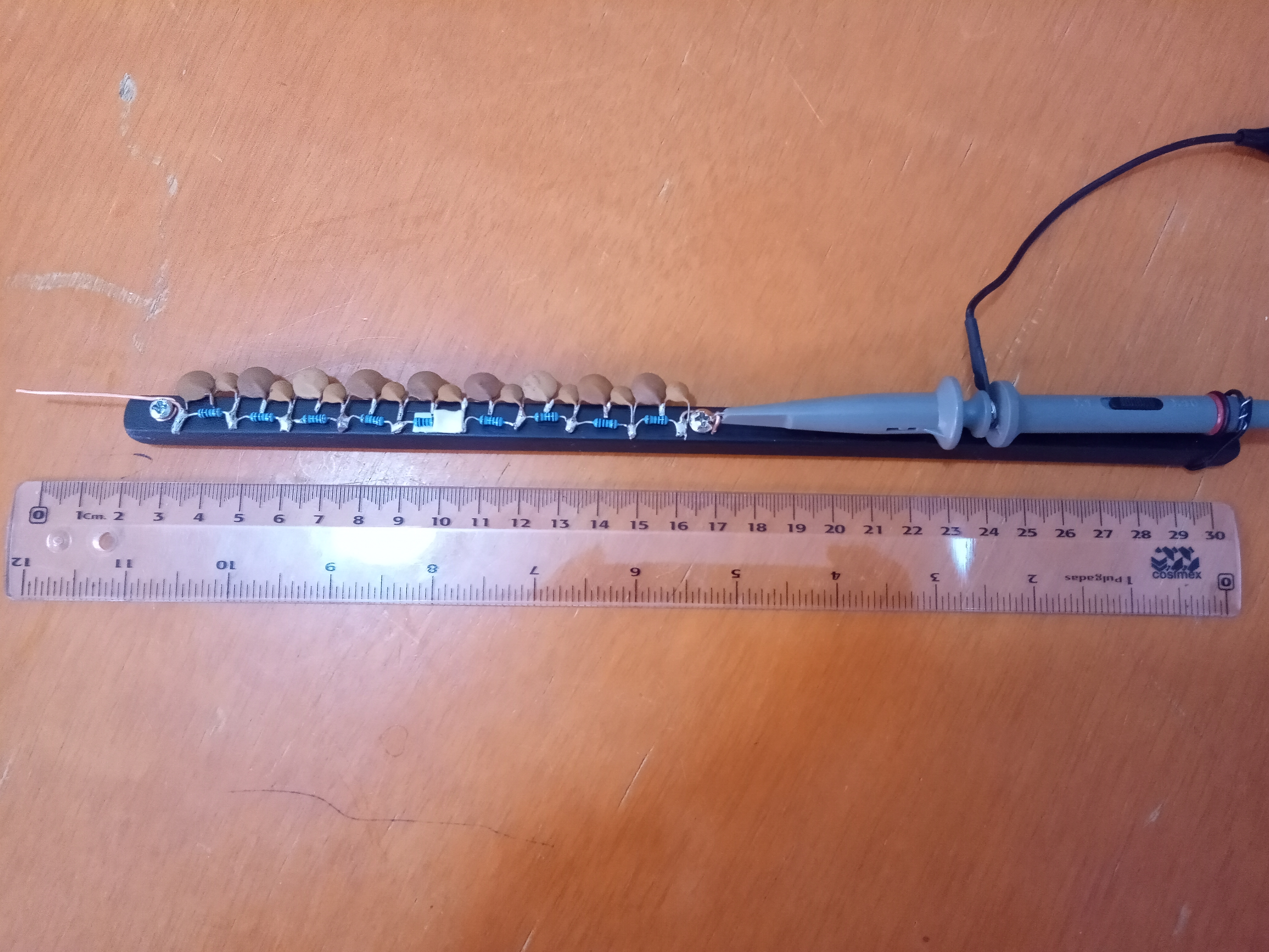
I have 28 volts on the antenna, with the probe at x10, would that be 280 volts? or something like that? if I increase C2 and C4 to 7.5pf, it reaches 34 volts, but the range near the antenna is reduced.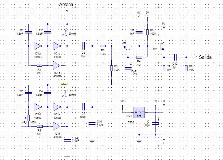
Adding inverters in parallel increases the antenna voltage.
"I have 28 volts on the antenna, with the probe at x10, would that be 280 volts? or something like that?" - [i]Goño[/i]
Yes, somewhere around there. I calibrated mine with an audio function generator that goes to 2MHz.
Is the black thing everything is mounted on plastic or wood? Wood could be a problem.
And where are your zip-ties? :-)
"if I increase C2 and C4 to 7.5pf, it reaches 34 volts, but the range near the antenna is reduced."
The capacitors are directly loading down the antenna, and reducing sensitivity. Though I guess you're making an analog Theremin so this maybe doesn't matter so much?
"Adding inverters in parallel increases the antenna voltage."
Yes, that should happen, more current to the coil.
You have interesting oscillators and an interesting mixer. Have you considered faster 3.3V CMOS, such as AHC? Faster devices can sometimes considerably lower the current, which usually means less heating drift.
Something else to consider: Maybe use a smaller inductor and larger capacitor in the fixed oscillator. It doesn't need a gigantic voltage swing, and you don't want it to be sensitive to external capacitance.
You must be logged in to post a reply. Please log in or register for a new account.

