New Moog Etherwave Guts Pix (& Repair)
I recently got my hands on one of the new Moog Etherwave Theremins to repair and thought I'd share some pictures of the guts along with some random thoughts (warning: there be criticisms ahead).
Symptoms were encountered after the unit was disassembled and reassembled by the owner, which was necessitated by the plastic trim strip covering the tuning holes in the top being way too tight to remove. Pushing on the bottom of the Etherwave would cause a loud clicking noise at the audio output, even when the mute switch was engaged. Prior to discovering that, tilting the Etherwave just so would do the same thing, and the mute indicator LED would flicker. Finally, the mute LED on the front panel remained permanently on, regardless of the position of the mute pushbutton.
The root cause was found to be a brass insert shorting togther two copper traces exposed via a gouge in the solder mask. This eventually blew the driver transistor Q17 (1AM, a SOT-23 version of 2N3904) for the LED, rendering it permanently lit. I desoldered the blown transistor, cleaned the pads, and installed a new one (like soldering a flea!). I also added some solder to the nicked traces to ensure connectivity, as the gouges were quite deep.
It's unclear how the PWB gouge happened, whether from the factory or from the required disassembly & reassembly to dislodge the trim strip. The clearances are quite small between the brass inserts and the bottom of the PWB (~1mm !) the edges of the inserts are quite sharp, and there were some sharp burrs sticking up a little from the insert threads - none of this is good, but I can't come up with the exact scenario that caused it. One thing that could perhaps produce it would be assembling it without installing the mounting screw in the center of the PWB, likely reducing the clearance further. I dunno, but the brass color and locations of these nicks coincide with the brass inserts, and there is very little holding the metal front and rear panels in position if misaligned.
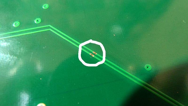
Above: The gouged and electrically exposed traces on the back of the PWB.
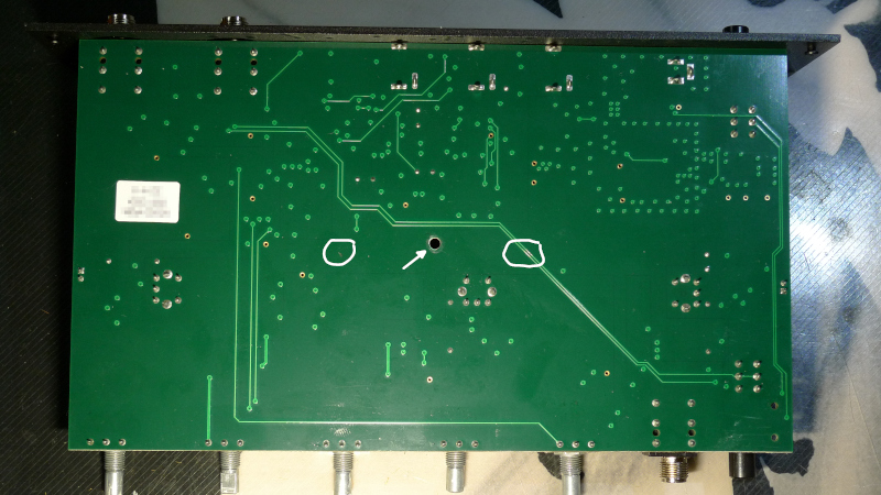
Above: The gouged traces circled on the right, a brass colored scratch appears opposite it on the left but there are no traces to harm in that location, and the arrow points to the PWB central mounting screw hole.
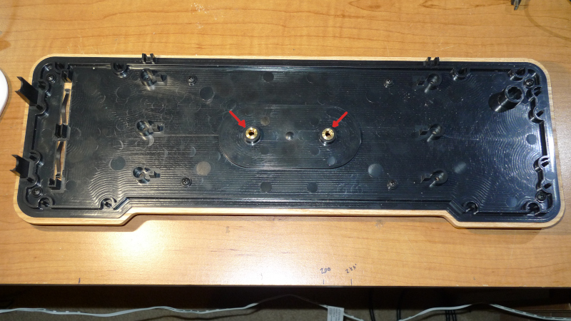
Above: The case bottom, showing the brass inserts used to hold the Claravox style quick release. Note how far away the screws are that attach the plastic to the wood bottom, allowing the plastic to flex and wobble a bit on the stand, likely resulting in even less physical clearance to the PWB back.
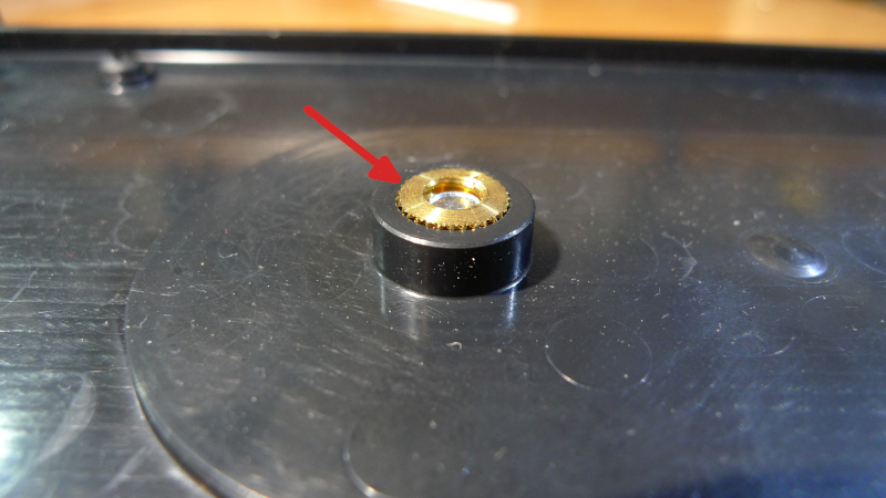
Above: A close-up of one of the brass inserts with the quick release screwed in from the bottom. The outer corners are quite sharp, and there were some burrs sticking up from the threads.
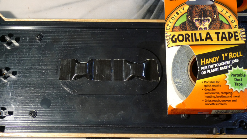
Above: To ward off future problems, I deburred the brass threads with a countersink and stuck some heavy duct tape over them. Note that a too-long screw could still cause trouble here as the PWB is only ~1mm away when assembled.
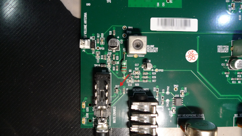
Above: The blown transistor Q17 (red arrow) has been replaced.
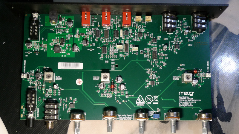
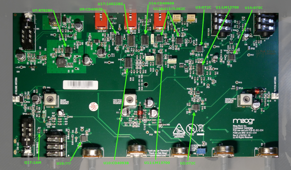
Above: The main PWB is modern high quality glass epoxy, and populated with surface mount components which are fairly difficult to service. I wish they'd used more old style through-hole components, but they're much more expensive than surface mount.
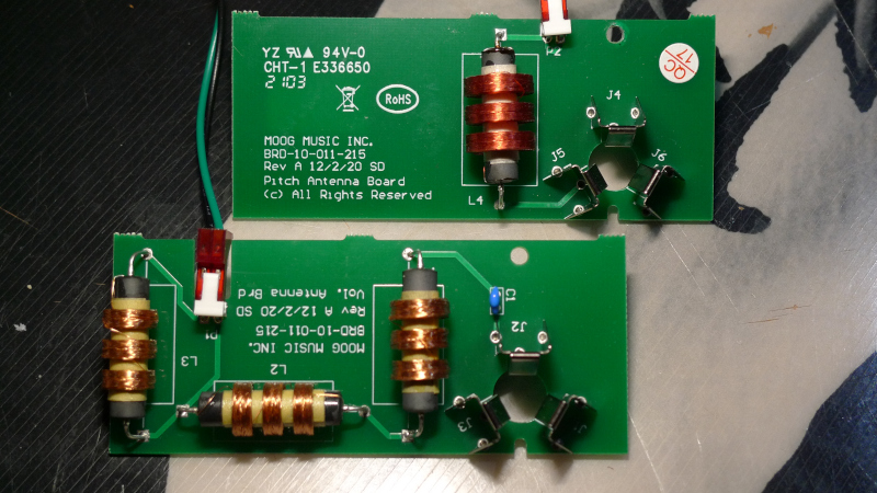
Above: The volume and pitch PWBs. The two smaller volume coils measure 2.5mH / 11DCR, the larger 4.7mH / 16DCR, and the series cap is 220pF (to prevent stalling when the loop is touched). The pitch coil measures 25mH / 56DCR. The volume side operates at 488kHz / 12Vpp, the pitch side 344kHz / 77Vpp. Weird that there's only a single pitch coil instead of the usual 3 or 4 on the EW and variants. I don't have tons of experience with various analog Theremins and don't own an EW anymore, but the pitch field felt somewhat tight to me, I was getting almost an octave by just opening and closing my (somewhat small) hand. Note there is no splooge added to physically secure the coils, and some heatshrink tubing would be nice to protect the fragile windings.
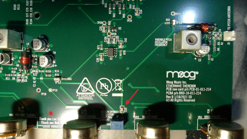
Above: The coupling trimmer is a variable pot in apparent series with C29 (I didn't measure these values). The control does work, though if you turn it too far CW (for max coupling) it strongly affects the tuning. (Note the ***GOOD VIBRATIONS*** misinformation! ;-)

Above: The PWBs installed in the top of the unit. The plastic posts that hold everything together are rather flimsy, and the screw threads going into them feel oversize for the holes and excessively tight. The pitch antenna board post was scarily twisting as I tightened the screw, so I used a bit of dry lube on all of the screws, and took care not to cut new threads. Use extreme caution here when reassembling! Turn the screw CCW until you feel it clunk, then proceed to screw it in.
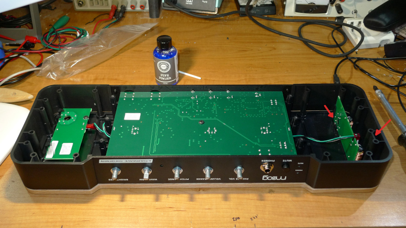
Above: The side plastic sections installed. The right-most arrow shows the physical stop for the volume loop, the left-most arrow shows no support for the longer end other than the PWB contacts, making the loop rather wobbly and the arrangement possibly fragile.
The antennas are solid metal, so they make up ~1/4 of the total weight, which seems a bit excessive. There are no EE / physics reasons for solid antennas - tubes made of tinfoil would work equally well here - but Moog Inc. seems enamored with very heavy rod stock lately.
The volume field knob seems more like the Big Briar than the EW, not a lot of change over the full range of the knob, but it's been years since I've experienced either. The field shaping is much too gradual for my tastes with no obvious knee action, but probably typical of EWs in general.
I tested the CV outs: The gate CV toggles from 0 to 9V and has some hysteresis; the volume CV goes from 0 to ~4V if the volume range knob is set to max; the pitch CV goes from -2.27 @ 0Hz to +5.12V @ 4.26kHz (rod touch) with 1V / octave.
Also tested the mute input. It could use another volume control for the rear audio output IMO.
Many more and higher resolution pix here: https://www.mediafire.com/file/hk16i80jo923ejm/Etherwave_guts_pix_2022-06-03.zip/file
A short video showing the looseness of the antenna mounts: https://www.youtube.com/watch?v=VoOUEtv4Tq8
It probably seems like I came here to bury the new EW, rather than to praise it! The new cabinet is quite attractive looking, I like the oak and the recessed knobs. And it's nice to have the CV and ESPE01 stuff integrated into the design. But there isn't anything all that new to the design compared to the previous EW models, and the large amount of plastic used structurally seems a bit sketchy to me.
I haven't had a lot of time to review the pix and scrounge part numbers off of them - so let the reverse engineering begin!