


First post in this construction forum to check if I'm on the right path in building a Theremin (partly) my way...
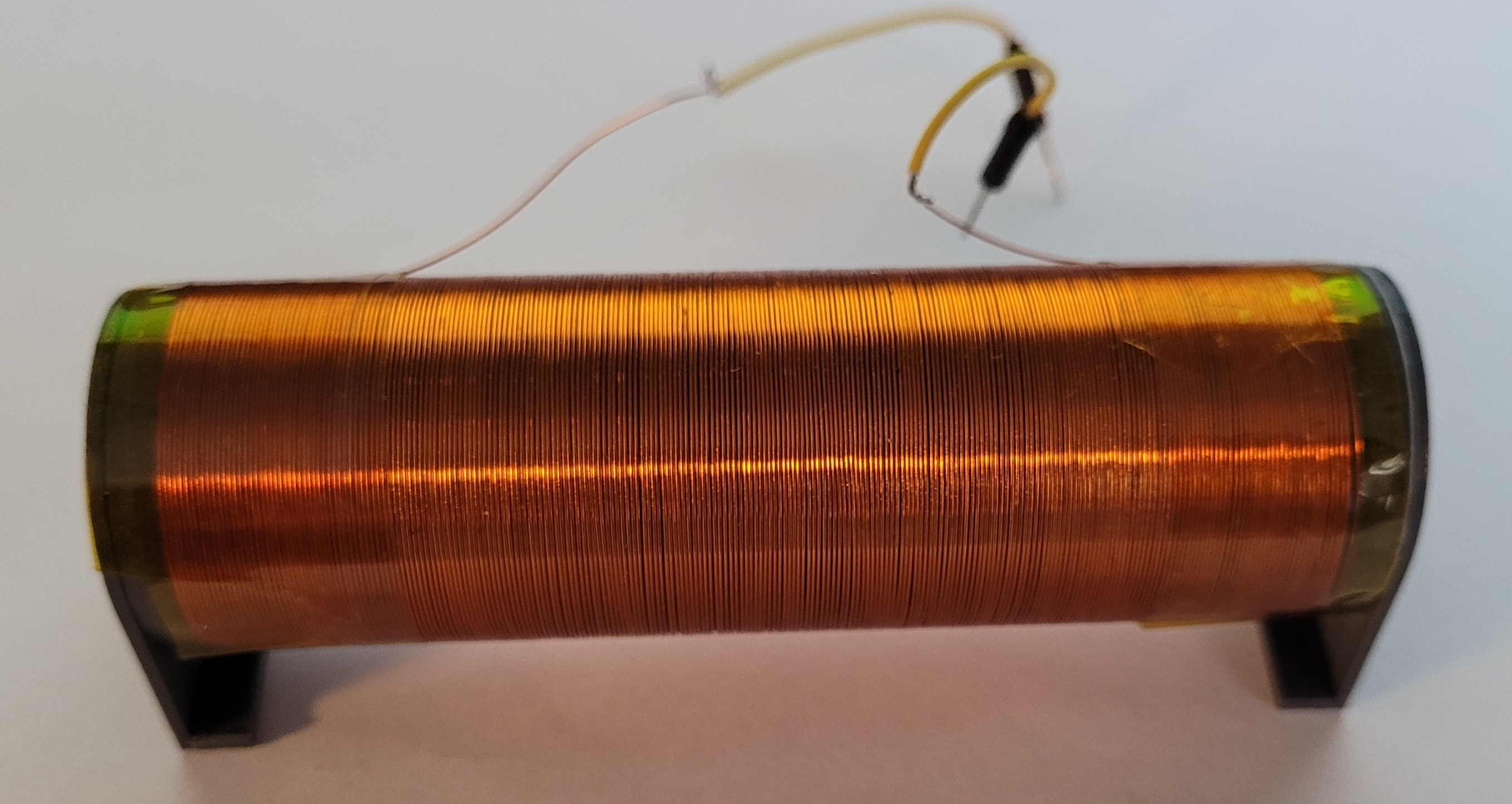
Since I'm in the possession of a 3D printer, I might as well put it into use by building a Theremin, and the first thing I did was printing a coil body, coil length = 9cm, diameter = 3cm, wire diameter = 0.2mm.
As Dewster suggested (somewhere, can't reproduce the thread), I connected one side to a function generator and the other side to an antenna (which in this case is a 50cm long wire). Have a scope channel connected to the output of the signal generator and an other channel of the scope to the junction coil/antenna. (probes are 10x 10Mohm, 14pF)
That's what I did and this is the result:
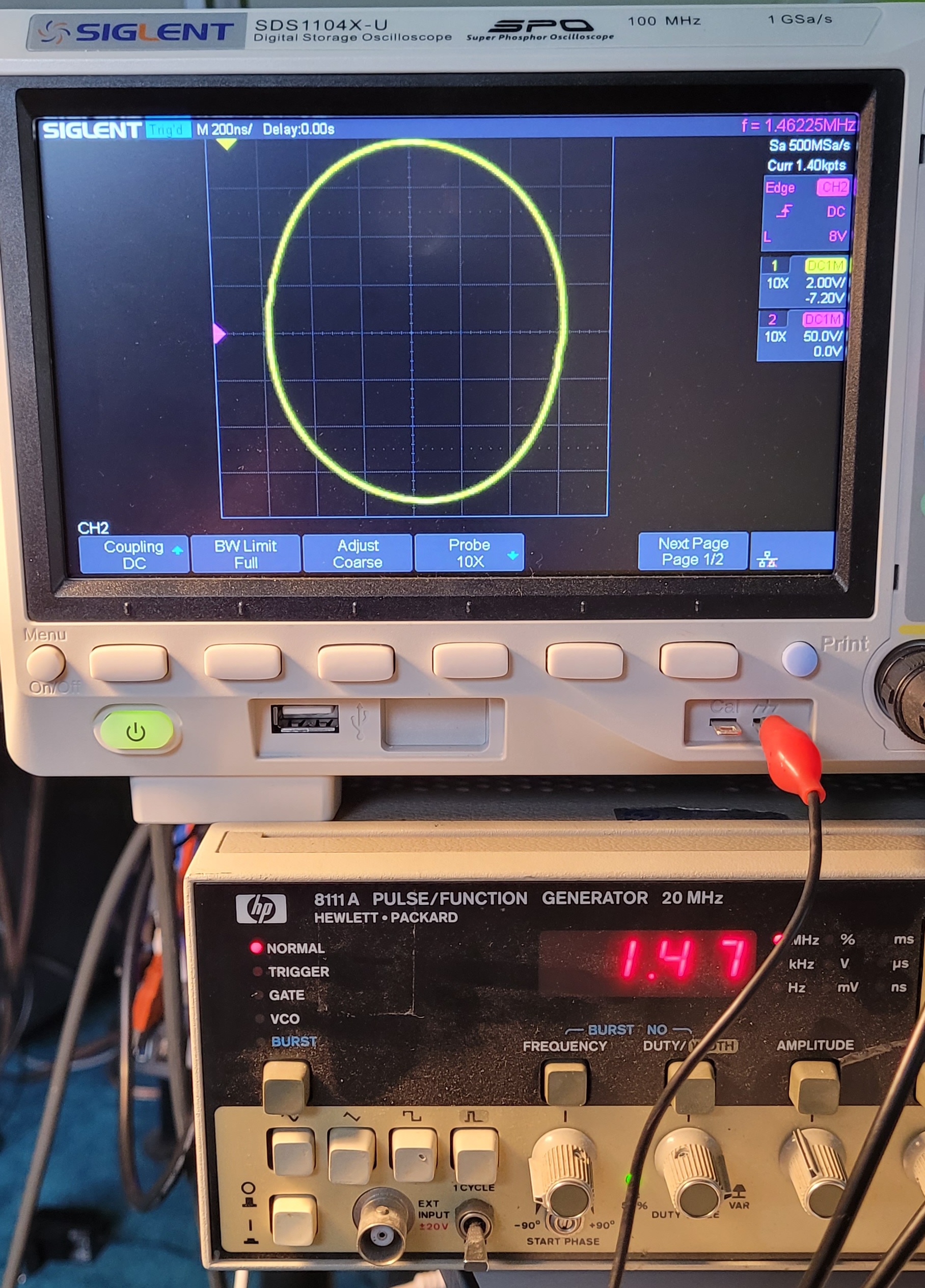
The resonance frequency is 1.47MHz, the phase is 90° (a Lissajous circle) and the Q-factor (correct me if I'm wrong) is about 25 (50 volt per division / 2 volt per division)
If I move my hand to and away from the antenna, I can see amplitude of both the signals and the phase of relationship change.
Obviously the impedance of the coil plus antenna is maximal at the resonance frequency, away from the frequency the impedance is lower, so it will affect the amplitude of the function generator.
I have a questions where I didn't find any answers for:
Is there a reason why the volume and pitch oscillators are adjustable while the reference oscillators are fixed? I am thinking about building the pitch and volume oscillators "fixed" so they can be set for the best possible behavior, while the reference oscillators will be a programmable waveform generator that is crystal stable but microprocessor controllable.
When using the clock generator of say an Arduino (16MHz) the resolution of this generator is 0.064Hz and crystal stable!


