Let's Design and Build a (mostly) Digital Theremin!

Posted: 7/18/2023 12:15:33 PM
dewster

From: Northern NJ, USA

Joined: 2/17/2012

Come On Feel The Noise

Was playing around with gated noise yesterday. Up until now the gating source has been the phase modulator from oscillator 0, but I thought it might be interesting to have it be a controllable mix (via 1_OSC:xmix) of all three oscillators. It seems useful and so it will likely be in the next SW release. Demonstrated here via yet another monster type voice, with tracking breathy "puff" type sounds:

https://d-lev.com/audio/2023-07-17_monster2.mp3

I think this software modification improves the steam train preset too (after a bit of fiddling around with it):

https://d-lev.com/audio/2023-07-17_train2.mp3

Posted: 7/21/2023 10:04:03 AM
Buggins

From: Porto, Portugal

Joined: 3/16/2017

Buggins, thanks for doing all of this FPGA board research!  FPGAs with only a single PLL inside it may be a problem generating 48kHz and higher powers of 2 needed for PCM audio?  I do wish they would use oscillators with base frequencies that could offer broader options here.

All mentioned boards in my recent list (colorful and icesugar pro) at least have 2 PLLs.

Posted: 7/21/2023 12:42:59 PM
dewster

From: Northern NJ, USA

Joined: 2/17/2012

"All mentioned boards in my recent list (colorful and icesugar pro) at least have 2 PLLs."  - Buggins

Ah, thanks for that clarification!

Posted: 7/29/2023 4:57:41 PM
ekahn

Joined: 11/2/2022

Condensing a few months of D-Lev related efforts into a single post:

First off, I successfully replicated the entire D-Lev with surface-mount parts, an integrated DAC chip, and custom-wound inductors from an Alibaba supplier

It's now in Eric's possession, along with a large batch of the custom inductors I ordered to build with.

See me talk about it here...

Design files for the PCBs are here. I've currently made 5, not planning on putting together any more, but I used it to lure in a lot of folks from outside the theremin community who are interested in helping with the project!

I'm mirroring all of Eric's open-source material on GitHub. It's currently private. I want to get it organized neatly before opening to the public, but currently it's the same material on https://d-lev.com/source.html.

This Lattice FPGA, mentioned by Buggins here, seems like it might have enough resources to run a D-Lev, and only costs $6. I now have a few dev boards on hand to play with.

Finally, hoping Eric can get his waiting list cleaned up, I ordered enough FPGAs and inductors to build 25 more D-Levs. So, hopefully there's movement in that direction. I'm hoping to do some minor PCB revisions (nothing radical like the photo above), reduce the soldering requirements as much as possible, and hopefully then have a D-Lev "kit" build that will be easier to source parts for and assemble.

Also: has OpenEMS been tried to do antenna simulation yet? Side benefit, it can then be used to make amazing visualizations...

Posted: 7/31/2023 1:03:47 PM
dewster

From: Northern NJ, USA

Joined: 2/17/2012

That's a lot of hard work Evan!  I'll test those coils shortly and get back to you.  Will also attempt to fit things into that Lattice FPGA, thank you for investigating this!

Posted: 8/12/2023 12:48:34 PM
dewster

From: Northern NJ, USA

Joined: 2/17/2012

Constraining Q

Was on vacation last week and had some thoughts about Q.  It might be good to have excess Q and then knock it down a bit via a large value resistor from antenna to ground, sort of like how excess opamp gain gives very controlled gain via feedback.  The C divider would be less fiddly, and experiments I did years ago IIRC showed a significant noise reduction too (mains hum IIRC) probably due to the RC filter formed between it and the antenna C.

I mean, you generally want as big a Q as possible, because it is a direct multiplicative gain figure in the oscillator feedback loop, as well as for the antenna voltage swing, so it's an SNR^2 thing, and so you need really good reasons to significantly reduce it.

Posted: 8/12/2023 3:35:57 PM
dewster

From: Northern NJ, USA

Joined: 2/17/2012

Inductive Reasoning

Following up on the clever LCR / gyrator-based derivation of the Sallen-Key filter article I linked to here a while back: http://www.thereminworld.com/forums/T/28554?post=222796#222796

It's got me thinking there may be a way to replace the Theremin inductors with capacitors and op-amps, which would be something of a holy grail.  

Consulting Don Lancaster's "Active Filter Cookbook" there are a couple of versions of the Sallen-Key low pass topology.  One version is equal component value, where both resistors are equal, as are both capacitors, and Q is then controlled via the amplifier gain (gain = 3 - 1/Q).  The other version is unity gain, with Q controlled via the capacitor ratios, specifically the larger feedback C is set to 4*(Q^2).  This second version is most interesting because Q is fairly insensitive to variations in the smaller capacitor value, which also is conveniently referenced to ground.  Anyway, I've been playing around with it some in LTSpice:

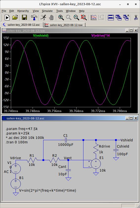
The Q here is sqrt(10000pF/10pF/4)=15.  There is a very nice quadrature at resonance, so the D-Lev DPLL construct could be applied here too.  It is *quite* sensitive to gain, even slight variations from 1 really kill the Q, so I'm using excess op-amp gain (10k here) knocked down via negative feedback to get a fairly precise gain of 1.  The feedback is after Rdrive, a resistor that might be useful to reduce oscillation - unity gain feedback is the least stable for an op-amp, and driving C can also be problematic.  The unity gain buffer output could be used directly for drive and antenna shielding too, something I'm burning to experiment with.  Drive shielding might enable having the oscillators on the main PCB.

Operating point is 50kHz, which could be lowered by increasing R1 & R2, but that would introduce more thermal noise, not sure where the happy medium might be.  The single pole roll-off of the op-amp open loop gain would certainly be a factor here.  Might be interesting to run it at audio DAC rates and do the quadrature phase loop lock in software.

Clearly one would need sufficient VCC to accommodate the resonant peak.  Drive amplitude would likely need to be reduced.  I'm thinking R2R ladder here to supply drive phase directly, rather than via dither, though dither may still be required for input sampling.  Lower Q would allow a lot of dithering actually.

Anyway, it looks promising in simulation and ticks a lot of design boxes, who knows yet if it is at all practical for Theremin electric field use.

Spice file: [LINK]

[EDIT] Also wanted to add that circuit currents in general are quite low too, which is good from a heating drift standpoint.

Posted: 8/14/2023 12:38:18 PM
dewster

From: Northern NJ, USA

Joined: 2/17/2012

An excellent gyrator design reference: https://sound-au.com/articles/gyrator-filters.htm

Posted: 8/14/2023 5:55:21 PM
JPascal

From: Berlin Germany

Joined: 4/27/2016

I use in my designs passive T-filter after antenna and the high inductive coils to reduce/avoid the hum modulations. Oscillator remains stable. Q is reduced.

Posted: 8/14/2023 7:37:35 PM
dewster

From: Northern NJ, USA

Joined: 2/17/2012

"I use in my designs passive T-filter after antenna and the high inductive coils to reduce/avoid the hum modulations. Oscillator remains stable. Q is reduced." - JPascal

Fascinating!  Could you share your circuit?

You must be logged in to post a reply. Please log in or register for a new account.